Virtually Imaged Phased Array
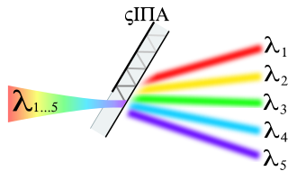
A Virtually Imaged Phased Array ( VIPA ) is a dispersive component which, similar to a prism or a diffraction grating, splits the light into its spectral components . It is a modification of the Fabry-Pérot resonator and works almost independently of the polarization of the light. In contrast to prisms or gratings, it has a significantly higher dispersion , but has a smaller free spectral range . It thus resembles an echelle grating that is mostly used in reflection , since high diffraction orders are also used here. The VIPA, on the other hand, can be operated as a compact component in transmission and transmits almost 100% of the light.
Origin of the term
A Virtually Images Phased Array is the optical analog of the phased array antenna known from radio technology. The VIPA could literally be translated as a virtually mapped phase-controlled field , since multiple virtual optical images of a light bundle in the VIPA create a phase-controlled field from individual sources, as will be explained later.
History and previous uses
The VIPA presented by Shirasaki in 1996 has very good dispersion properties, which are particularly interesting for the field of optical communication technology. So far, the applications are mainly in research, an overview of which is given below.
It was introduced as a component for the optical wavelength division multiplexing process (WDM), whereby a channel separation with a distance of 0.8 nm was achieved. This application was taken up again nine years later in order to achieve WDM with a channel spacing of 24 pm (3 GHz). Furthermore, by using wavelength-dependent path lengths, due to the angular dispersion of the VIPA, a compensation of chromatic dispersion of fibers was realized. This has been expanded as a tunable system using adjustable mirrors or a spatial modulator for light (SLM). In addition to systems for waveform generation in the radio frequency range , systems for pulse shaping by combining VIPA for high-resolution wavelength splitting or recombination and an SLM were demonstrated. In this way, it was also possible to compensate for polarization mode dispersion . A VIPA in combination with a diffraction grating can produce a two-dimensional spectral splitting of the light similar to an Echelle spectrograph , which was initially implemented for high-resolution WDM (> 1000 channels), but has now also been used in the field of infrared spectroscopy . This concept can be implemented in combination with a high-resolution spectrometer and a spectrally limited pulsed light source (e.g. femtosecond laser ) in a confocal microscope setup, which enables both spectrally coded imaging and material ablation (using a tunable laser) with the same measuring head.
Structure and functionality
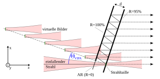
In principle, the VIPA is a slightly modified Fabry-Pérot resonator that is operated at a defined tilt angle. The optical resonator is formed by a glass or air gap, which is surrounded by an ideal mirror (R = 100%) and a partially transparent, highly reflective mirror (R ≈ 95%). The side of the ideal mirror has an antireflection-coated entrance window through which a light bundle focused in the x-direction onto the rear side of the resonator is coupled. A cylindrical lens is usually used for this, the design of which then defines the coupled angle range.
As a result of multiple reflections in the resonator, the light bundle is coupled out several times laterally offset in the x-direction at the partially transparent mirror. On the output side, a series of virtual sources are thus superimposed, which are arranged at a defined distance both along the x-axis and along the z-axis. This is where the name Virtually Imaged Phased Array comes from , as several virtually imaged sources are superimposed as a phase-adjusted field . The superposition of these virtual light bundles creates an interference pattern in the far field . Certain wavelengths are only allowed to propagate in defined spatial directions due to interference, which creates an angular dispersion . Strictly speaking, these spatial directions are only resonances in the angular range, but are usually called diffraction orders in connection with the VIPA , since the VIPA represents an angularly dispersive component here. This angular dispersion can be displayed on a screen using a converging lens. If the coupled-in light bundle and the first back reflection are clearly separated from one another and their beam profile is also not clipped, no further “classic” diffraction of the light bundle occurs. This means that the light is only coupled out in directions that are within the angular range of the coupled-in light bundle.
Resolving power
Similar to the resolving power of the diffraction grating , in which the number N of illuminated grating elements determines the sharpness of the diffraction orders, the quality of the resonances with the VIPA is defined by the degree of reflection of the VIPA rear surface. To put it simply, a high degree of reflection means that light stays "longer" in the VIPA and thus more overlapping, virtual sources arise, which sharpens the diffraction orders. In contrast, with a lower degree of reflection, the light decouples quickly, fewer virtual sources overlap and the diffraction pattern loses its quality.
Viewed better, this phenomenon can be described more precisely using the parallel to the Fabry-Pérot resonator. In the same way, with the VIPA, a higher degree of reflection leads to a higher resonance quality, i.e. sharper diffraction orders. With regard to the Fabry-Perot resonator, the diffraction pattern of the VIPA is nothing more than a section through the interference ring pattern, but in a very limited angular range> 0 degrees.
Improved resolving power
A constant degree of reflection of the VIPA rear surface generates a Lorentzian light power distribution on the coupling-out side , which has a negative effect on the resonance quality , i.e. the sharpness of the diffraction orders. This can be improved by providing the rear surface with a reflectance that falls linearly starting from the coupling window. This leads to a Gaussian-like, decoupled beam profile and improves the resonance quality.
Law of dispersion
An analytical calculation of VIPA's dispersion behavior was first derived in 2003 by Vega on the basis of the theory of plane waves . Several simplifications have been adopted here, which lead to inaccuracies in the model. Xiao developed a much more precise model in 2004 based on Fresnel's diffraction theory . From this Xiao derived the law of dispersion
from. The order of diffraction corresponds to the light wavelength in the vacuum, the refractive index of the resonator, the thickness of the VIPA, the diffraction angle, the tilt angle of the VIPA and the angle of spread of the main ray within the VIPA, which can be calculated according to the law of refraction . In addition, Xiao's model also provides an analytical solution for the intensity distribution of the diffraction orders, i.e. an exact statement about the quality and thus the resolving power of the VIPA.
Free spectral range
For the telecommunications sector which is free spectral range ( english free spectral range (FSR)) another characteristic feature of a dispersive component. This states the range in which the wavelength or frequency of the light may vary without two adjacent diffraction orders of the two limit frequencies of this range overlapping. He also obtained according to Xiao speed of light to
Free angular range
If the associated dispersion angles of the VIPA are considered in relation to the free spectral range, this means that two neighboring diffraction orders of a certain wavelength enclose a defined angular range. This angular range is an important measure for an application, since it defines the uniqueness range in which a dispersion angle can be assigned to a specific diffraction order of a fixed wavelength. Viewed from a different perspective, wavelengths within the free spectral range for a defined diffraction order span a clear angular range, which is defined as a free angular range (FWB) and is based on the law of dispersion
With
and
can calculate.
literature
- M. Shirasaki: Virtually Imaged Phased Array . (PDF) In: FUJITSU Sci. Tech. J. , Vol. 35, 1, pp113-125. July 1999, accessed March 23, 2018 .
- P. Metz: Active micro-optics based on tunable thin-film resonators. (PDF) Dissertation. Retrieved March 23, 2018 (32 Mb). (Among other things, a tunable VIPA is dealt with)
Individual evidence
- ↑ M. Shirasaki: Large angular dispersion by a virtually imaged phased array and its application to a wavelength demultiplexer. In Optics Letters , Vol. 21, No. 5, 1996.
- ↑ S. Xiao and AM Weiner: An eight-channel hyperfine wavelength demultiplexer using a virtually imaged phased array (VIPA). In Photonics Technology Letters , Vol. 17, No. 2, 2005.
- ↑ LD Garrett and AH Gnauck and MH Eiselt and RW Tkach and C. Yang and C. Mao and S. Cao: Demonstration of virtually-imaged phased-array device for tunable dispersion compensation in 16 times; 10 Gb / s WDM transmission over 480 km standard fiber. In Optical Fiber Communication Conference , Vol. 4, 2000
- ^ S. Cao, C. Lin, G. Barbarossa and C. Yang: Dynamically tunable dispersion slope compensation using a virtually imaged phased array (VIPA). In LEOS Summer Top. Meetings Tech. Dig. , 2001
- ↑ Ghang-Ho Lee: Demonstration of optical tunable dispersion compensation with a virtually imaged phased-array based pulse shaper. PhD Thesis, Purdue University , 2006
- ↑ JD McKinney, DE Leaird and AM Weiner: Millimeter-wave arbitrary waveform generation with a direct space-to-time pulse shaper. In Optics Letters , Vol. 27, No. 15, 2002.
- ↑ VR Supradeepa, E. Hamidi, DE Leaird and Andrew M. Weiner: New aspects of temporal dispersion in high-resolution Fourier pulse shaping: a quantitative description with virtually imaged phased array pulse shapers. In: Journal of the Optical Society of America B , Vol. 27, No. 9, 2010
- ↑ H. Miao, AM Weiner, L. Mirkin and PJ Miller: ll-Order Polarization-Mode Dispersion (PMD) Compensation via Virtually Imaged Phased Array (VIPA) -Based Pulse Shaper. In IEEE Photonics Technology Letters , Vol. 20, No. 8, 2008
- ↑ T. A, Johnson and SA Diddams: Mid-infrared upconversion spectroscopy based on a Yb: fiber femtosecond laser. In Applied Physics B - Lasers an Optics , Vol. 107, No. 1, 2012
- ↑ KK Tsia, K. Goda, D. Capewell and B. Jalali: Simultaneous mechanical-scan-free confocal microscopy and laser microsurgery. In Optics Letters , Vol. 34, No. 14, 2009
- ↑ M. Shirasaki, AN Akhter and C. Lin: Virtually imaged phased array with graded reflectivity. In Photonics Technology Letters, Vol. 11, No. 11, 1999.
- ↑ A. Vega, AM Weiner and C. Lin: Generalized Grating Equation for Virtually-Imaged Phased-Array Spectral Dispersers. In: Applied Optics, Vol. 42, No. 20, 2003. Archived from the original ; accessed on March 23, 2018 .
- ↑ PDF S. Xiao, AM Weiner and C. Lin: A Dispersion Law for Virtually Imaged Phased-Array Spectral Dispersers Based on Paraxial Wave Theory, In IEEE Journal of quantum electronics, Vol. 40, No. 3, 2004
- ↑ PDF . P. Metz, H. Block, C. Behnke, M. Krantz, M. Gerken, J. Adam: Tunable elastomer-based virtually imaged phased array, In Optics Express, Vol. 21, Iss. 3, 2013.


