
Water tube boiler

A water tube boiler is one of several similar types of steam boilers . It is characterized by the fact that the water is routed in the pipes , in contrast to the shell boiler , where the flue gases are routed in the pipes. The water tube boiler can be used as a steam or hot water generator.
General
The simple shell boiler can be used with gas and oil firing systems for steam outputs of up to 25 t per hour and pressures of up to 32 bar. The shell boilers can no longer be used for higher outputs and pressures, as well as for the automated combustion of solid fuels. The materials to be used would be too strong, so that inadmissibly high stresses would arise in the materials during heating because the boiler could no longer follow the thermal expansion. It is therefore necessary to switch to the more complicated construction of the water tube boiler.
In a water tube boiler, the water is in tubes that run through the combustion chamber and are heated by the radiant heat from the combustion. The water in the pipes is heated and evaporated, the steam can be superheated in other pipes . Compared to the jackets of large-capacity water boilers, the water pipes have small wall thicknesses and are easy to manufacture so that high pressures and temperatures can be achieved with little use of material. For example, a 200 MW boiler from a lignite power plant can generate steam at 150 bar pressure and a temperature of 530 ° C. The total length of the pipes installed in this boiler is considerable, it is around 600 km.
Compared to shell boilers of the same capacity, water-tube boilers have a smaller water volume and are less sensitive to thermal stresses due to their construction. Compared to the shell boiler, this enables faster heating, but also makes the boiler more sensitive to water shortages. Furthermore, more attention must be paid to the water chemistry compared to the shell boiler, so that no scale builds up in the pipes. Deposits in the pipes impede the heat transfer to the water, so that the pipes can overheat locally and crack. Feuerungsseitig be soot blowers used to clean the heating surfaces in very dusty conditions.
history

The first design of the water tube boiler (original name water tube boiler) was the inclined tube boiler . The first usable boiler of this type was built by Ernst Alban from Schwerin, which was designed as a one-chamber boiler in 1840 and a two-chamber boiler in 1847. The tubes of this type of boiler are arranged at an angle of about 15 °. The tubes are rolled into forged steel water chambers on both sides. The chambers were provided with a closure opposite each pipe roll -in so that the pipes could be cleaned or replaced. The large chambers had to be stiffened with studs. The chamber formed a component, so that the term large chamber boiler has been used for this design of the down tube boiler. The flue gases are often diverted several times through the brickwork behind the combustion chamber so that the flue gases flow as vertically as possible onto the evaporator tubes. The chambers are connected to the boiler drum via a less heated pipeline . The water flows from the drum via a large pipe connection into the lower lying water chamber and is distributed over the evaporator pipes. Through the heat transfer from the flue gas flow, the water is heated and partially evaporated and rises in the evaporator tubes. The water-steam flow was directed from the higher chamber into the upper steam space of the drum.
In 1867 Stephen Wilcox patented the first sectional or partial chamber boiler . A continuous water chamber was no longer used, but the staggered evaporator tubes were connected by a wave-shaped sub-chamber so that one tube is always connected to the one above. These sub-chambers are connected to the inlet and outlet manifolds. The advantage of this arrangement is a higher elasticity, and it enabled mass production with individual adaptation of the number of rows of tubes and thus the steam output to the respective customer requirements.
The steam output at that time was 2.4 tons of steam per hour. The development of the seamless pipe by the Mannesmann brothers in 1886 was an essential prerequisite for the further increase in output .

Partial chamber boiler according to Babcock-Wilcox

Partial chamber with tubes
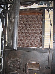
View of the front sub-chambers of a boiler from around 1900
.jpg)


The further development was the steep tube boiler . It is named after the steep, almost vertical arrangement of the pipes, which flow into a lower and upper boiler. Garbe built the first vertical tube boiler with straight tubes in 1904, followed by the Stirling boiler with curved tubes in 1906 , which allowed all tubes to be inserted vertically into the drum. The lower and upper boiler were riveted components into which the tubes were rolled. The advantage of the design is the lower space requirement, as the boilers increased in height compared to the inclined tube boilers. Furthermore, the complex chambers with the large number of closures and sealing elements were omitted. A partition wall is let in between the rows of pipes on the flue gas side. The front part of the tube rows is heated more strongly by the hotter flue gases than the tube rows on the downstream side of the flue gas. Due to the different heat transfer, the rear rows of pipes formed the downpipes, and in the more heated front pipes the water rose to the upper boiler and thus created the natural circulation. However, the water circulation of the first vertical tube boilers was rated worse than that of the inclined tube boiler. Around 1910 the diameter of the evaporator tubes was 80 to 100 mm, the operating pressures were around 15 bar, and the heating surfaces were up to 350 m². The specific steam generation was 12 to 18 kg / (m² h).

Steep tube boiler according to Garbe
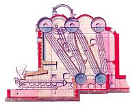
Stirling cauldron

.jpg)
In 1918, coal dust was first used in continuous operation to fire a water-tube boiler, which greatly increased the output per boiler. In 1916 a boiler in the Zschornewitz power plant produced 15 t of steam per hour at 14.7 bar and 350 ° C, in 1926 in the Klingenberg thermal power plant in Berlin it was already four times more, namely 80 t at 34.3 bar and 425 ° C. In the course of further technical development, operating pressures of 100 bar were reached in 1927/28. These more powerful boilers also required a greater fire output. With the higher flame temperatures, the formation of scale also increased, which is proportional to the temperature and vapor pressure. Two solutions were sought: treatment of the feed water so that no scale can occur or the use of boiler designs in which the evaporation takes place outside the combustion chamber, which was referred to as indirect evaporation or indirect evaporation .
One of the boilers with indirect evaporation is the Schmidt-Hartmann boiler developed by Wilhelm Schmidt and Otto H. Hartmann from 1922 onwards . This boiler consists of a closed high-pressure primary circuit, which releases its heat in an evaporation drum to an open secondary circuit, the pressure of which is around 20 bar lower than that in the primary circuit. The boiler is therefore also referred to as a two-pressure boiler . Another design with indirect evaporation is the Löffler boiler . In this forced circulation boiler , developed by Stephan Löffler in 1923 , the primary circuit is operated in the supercritical range and the live steam in the drum is generated by the overheating. Both types are no longer used today. Although they protect the boiler from deposits, they could not prevent them on the working machines.

Schmidt boiler

Löffler kettle


A further increase in the operating pressures in natural circulation boilers is limited by the increasing wall thickness of the drums, and for physical reasons they can only work under the critical pressure of 220 bar. For higher pressures, forced circulation boilers or once-through boilers that do not require a drum must be used .
The technical limits of steam generation are currently at pressures of 300 bar in the supercritical range of water and at overheating temperatures of 600 ° C. In the course of development, the steam output of a power plant unit has risen to currently 2,000 t / h.
Designs
A distinction is made according to design
- Natural circulation boilers , which are only fed with water from the condenser by the feed pump and in which the water circulates naturally between the upper and lower collecting tanks ,
- Forced circulation boilers in which the water circulation is ensured by a circulation pump ,
- Forced flow boilers in which the water is pumped through the pipe system in one direction.
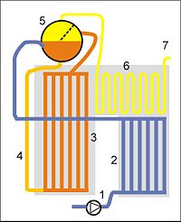
Natural circulation boiler
1 SPW pump
2 SPW preheater
3 evaporator
4 downpipes
5 drum
6 superheater
7 to turbine
SPW = feed water
Forced circulation boiler
1 SPW pump
2 SPW preheater
3 evaporator
4 downpipes
5 drum
6 superheater
7 to the turbine
8 circulation pump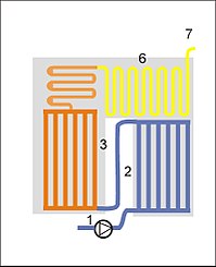
Once-through boiler design: Benson boiler
1 SPW pump
2 SPW preheater
3 evaporator
6 superheater
7 to the turbine
Forced flow boiler design: Sulzer boiler
1 SPW pump
2 SPW preheater
3 evaporator
6 superheater
7 to the turbine
9 water separator


construction
The bulk of the evaporator is largely self-supporting (the tube walls consist of tubes welded together). The rest of the structure of a water tube boiler consists essentially of steel profiles with foundations of concrete . Alternatively, reinforced concrete can also be used for the structure. The outer walls of the structure are thermally insulated and clad with metal sheets for weather and noise protection .
Typical pipe dimensions are:
- Preheater: 38 × 3.5 mm
- Evaporator: 60 × 5 mm
- Superheater: 32 × 5 mm
Use of the boiler types
Natural circulation steam generator:
- Fluidized bed / waste incineration
- Heat recovery steam generator with horizontal flue gas flue
- Grate furnaces
- Oil, gas, pulverized coal firing with small outputs up to 300 t / h steam
- Power plant steam generator (USA) up to 180 bar
Forced circulation steam generator:
- Power plant steam generator between 180 and 200 bar steam pressure
- Heat recovery steam generator with horizontal heat exchangers
Forced once-through steam generator:
- Power plant steam generators (Europe, Russia, Japan) with subcritical steam parameters
- Power plant steam generator with supercritical steam parameters
- High temperature reactor
safety
Water-tube boilers are pressure equipment within the meaning of the Pressure Equipment Directive 2014/68 / EU and may only be placed on the market if the manufacturer has demonstrated through a conformity assessment procedure with the participation of a notified body that the basic safety requirements of the directive have been met. The manufacturer affixes the CE mark and issues an EC declaration of conformity . Harmonized product standards for water tube boilers are:
- EN 12952-1 to 17: water tube boilers
When using this standard, the manufacturer can assume that he meets the basic safety requirements of the directive (presumption of conformity).
literature
- Friedrich Münzinger : Steam power: calculation and behavior of water tube boilers generation of power and heat. A manual for practical use . Springer-Verlag, 2013, ISBN 978-3-642-53056-2 ( google.de [accessed October 14, 2018]).
Individual evidence
- ↑ a b Dennis Pudeck: water tube boiler, forced flow boiler, water boiler. Georg Hagelschuer GmbH, accessed on October 14, 2018 (German).
- ^ A b Walter Mentz: German ship engineering . In: German shipbuilding 1913 . Carl Marfels Aktiengesellschaft, 2012, ISBN 978-3-86444-502-6 , p. 125 ( google.de [accessed October 14, 2018]).
- ↑ Münzinger, p. 5
- ↑ Münzinger, pp. 17-18
- ↑ Münzinger, p. 6
- ↑ Hans-Burkhard Horlacher, Ulf Helbig: Pipelines 1: Fundamentals, pipe materials, components . Springer-Verlag, 2016, ISBN 978-3-642-39782-0 , pp. 11 ( google.de [accessed on October 14, 2018]).
- ↑ a b Münzinger, p. 8
- ^ Karl Strauss: Thermal power plants: From the beginnings in the 19th century to the final phase of their development . Springer-Verlag, 2016, ISBN 978-3-662-50537-3 , pp. 88–89 ( google.de [accessed October 14, 2018]).
- ↑ Maximilian Ledinegg: Steam generation steam boiler, furnaces: including nuclear reactors . Springer-Verlag, 2013, ISBN 978-3-7091-8150-8 ( google.de [accessed on October 14, 2018]).