
Truck-mounted concrete pump
.jpg)
A truck-mounted concrete pump is a mobile pump for pumping concrete . Their area of application is the construction of buildings, bridges or dams . Concrete with grain sizes of up to 63 millimeters can be pumped, whereby the height of the concrete placing booms can be up to 100 meters. The truck-mounted concrete pump is legally classified as a self-propelled work machine.
A truck-mounted concrete pump consists of a truck (chassis), a pumping system and, optionally, a placing boom.
The invention
Inadequacies in dealing with the conventional casting tower gave the engineers Max Giese and Fritz Hell the idea in 1927 of pumping the concrete from the concrete mixer directly to the point of use. The main thing was to keep the power consumption as low as possible compared to the casting tower method. The reduced water content of the concrete in the pumping process not only saved energy, but also allowed the material to set faster and more firmly. Gravel or broken stone material was used. It was possible to pump up to a height of 38 meters and a distance of 120 meters.
Pumping systems
Piston pumps
Concrete pumps have been used as single-piston pumps in Germany since the 1920s. Today, double piston pumps are predominantly used, which are hydraulically driven by electric or diesel motors using oil pumps . The delivery pistons are hydraulically connected to one another via drive cylinders and work in push-pull.
The core pump consists of
- hydraulic drive cylinder,
- Delivery cylinder with delivery piston,
- water tank connected in between,
- Concrete funnel with agitator,
- Pipe switch,
- lever
- Switching cylinder for transfer tube.
functionality
The returning delivery piston of one delivery cylinder creates a negative pressure, the medium from the feed hopper is sucked into the cylinder. At the same time, the advancing delivery piston pushes the contents of the other delivery cylinder through the transfer tube into the delivery line. At the end of the stroke the pump switches over, that is, the transfer tube swivels in front of the other filled delivery cylinder and the delivery pistons reverse their direction of movement.
In order to clean the pump or to loosen line blockages when pumping, every machine can also pump "backwards". The pumping back function is only the reversal of movement of the delivery piston through a hydraulic switching valve, while the transfer tube remains in its position and is only moved by the switching cylinders into the opposite switching position when the end position is reached. Piston pump units are pre-assembled as “core pumps” and, depending on the intended use, can be mounted on chassis as “truck-mounted concrete pumps” or on various subframes as stationary, construction site or tunnel concrete pumps.
The drives for concrete pumps are now exclusively hydraulic , whereby the control variants of the individual manufacturers differ. Variants are purely hydraulic sequential controls, electrohydraulic sequential controls, drives in open and closed hydraulic circuits, single and dual circuit controls and free-flow hydraulics. Each system has certain advantages and disadvantages.
Important performance factors are
- Delivery pressure,
- Machine weight,
- Price and
- Complexity of the system.
For these reasons, many variants have existed in parallel for a long time. With piston pumps, pressures in the pumping medium of up to 400 bar and flow rates of up to 200 m³ / h are achieved today.
Rotor pumps
The rotor pump is a simple, compact pumping system that works without a special concrete slide. Concrete is delivered by rollers that rotate in the rotor housing and squeeze the delivery hose (peristaltic pump ). This means that the rotor pump is the only system on the market which, when properly adjusted, represents a completely leak-proof delivery system.
functionality
A vacuum pump constantly creates negative pressure in the rotor housing . The higher, atmospheric air pressure on the concrete surface in the agitator tank and the static pressure of the concrete fill the pump hose directly behind the pressure roller up to the full cross-section with concrete. In the rotor housing, the delivery hose (pump hose) is pressed together by the continuous rolling of two pressure rollers, which are offset by 180 degrees from one another. The fresh concrete in front of the pressure roller is thus pressed evenly into the delivery line. Behind the pressure roller, the hose straightens up again as a result of the negative pressure in the rotor housing and thus develops a suction effect towards the feed hopper. The direction of rotation of the rotor drive is reversed for pumping backwards. In this way, the rotor sucks concrete out of the delivery line and pumps it back into the feed hopper.
The rotor pump is driven by an oil-hydraulic gear motor, whereby the delivery rate can be controlled continuously from zero to maximum, depending on the speed of the rotor. The service life and wear costs of this pump system are almost exclusively dependent on the conditions that act on the pump hose. The rotor pump system is now valued as being very environmentally friendly because it works with little noise (no switching noise as with piston pumps). It is characterized by a constant speed and smooth running.
Hardly any residual concrete remains in the feed hopper, as residual quantities can still be sucked into the delivery hose. In addition to concrete, other media such as water, self-leveling screed and fine mortar can also be pumped . The rotor system allows pressures in the pump medium up to a maximum of 30 bar and flow rates up to 60 m³ / h. This pump system is mainly used for truck mixer concrete pumps.
Gate systems / transfer tube
The heart of a concrete pump, in the mechanical part, is the concrete slide (pipe switch) with a wide variety of designs such as flat slide, wedge slide, knee slide, flapper, swivel tube, S-tube, trunk, rock slide, delta tube switch and CS tube switch. The rotor pump is the only pump system used that does not require a slide and is not considered here.
Only after a long period of practical use of the various slide systems do all the advantages and disadvantages of the individual systems emerge. In the pipe variant, the frictional resistance is more favorable due to the smaller sealing surface compared to other valve structures. The sealing of a pipe switch to the delivery cylinders or the pump outlet can be carried out technically easier and better. The transfer valves are almost absolutely leak-proof, so that water can now be pumped using concrete pumps without any problems. Concrete pumps are therefore also used as water pumps for cleaning the delivery line on some large construction sites. This is only feasible to a limited extent with other slide systems such as the flat slide.
The requirement for a good concrete slide is first and foremost tightness, since during the pumping process every gap, especially under high pressure, can lead to the concrete bleeding (i.e. water and fine substances are pressed out of the concrete mixture) and thus to concrete settling (crown formation). This results in bottlenecks in the concrete slide and thus higher pumping pressures, restricted pumping ability and, in extreme cases, stoppers directly at the pump. Another requirement of a good concrete pusher is quick switching between the end positions in order to have as short a concrete flow break as possible during the switchover process, so that the concrete flow is as continuous as possible. A good concrete pusher is also expected to move to its new end position as calmly, attenuated, quietly and vibration-free as possible, despite being switched through quickly. This reduces vibrations of the entire machine and rocking of the placing boom during pumping. These demands on modern concrete gate valves are safely mastered today. An additional, important requirement for concrete scrapers is wear resistance, not least for reasons of economy and service friendliness. If necessary, the operator's workshop or a technically experienced pump operator should be able to replace a concrete slide himself without a specialist. Manufacturers try to meet these requirements with new, wear-resistant materials or after-treatment of the valve parts. Since the wear behavior is very much dependent on application criteria such as the hardness of the aggregate , flow rate and pressure, a more or less better wear behavior can only be recognized by comparing the throughput quantities and the construction site conditions.
Concrete placing booms
The truck-mounted concrete pump with a concrete placing boom is the most widely used concrete pump in many countries today, with the placing boom defining the structure of the machine. The essential criteria for a truck-mounted concrete pump, in addition to the pumping capacity, are the reach of the placing boom, the type of folding (also known as folding kinematics ), the number of cantilever arms, support widths and the minimum unfolding height.
The market offers a very large range of concrete placing booms up to a maximum reach of around 100 m. The maximum height of the vehicle when folded is less than 4 m, the max. As with the chassis, width is 2.50 m. The truck-mounted concrete pump is classified as a self-propelled machine, which means that it is subject to different approval regulations than transport traffic. In September 2012, the Chinese manufacturer Zoomlion presented the largest truck-mounted concrete pump in the world to date: The concrete placing boom of the 101-meter-high pump, which is mounted on a 7- axle Scania chassis, is divided into seven segments; the top four are made from carbon fiber to reduce weight .
Structure / functionality
The individual arms of a concrete placing boom are box-type. They are moved hydraulically. Articulated joints with large angular ranges, together with the powerful slewing mechanism with a large swivel angle, result in very good flexibility when transporting the concrete to the place of application, over obstacles and even through small openings such as windows. Conveying lines and risers usually consist of standardized straight pipe sections and pipe bends. These are thus easily exchangeable. Standard shell couplings also serve as swivel joints and pipe connectors. The pipe joint at the end of the mast acts as a fall brake and reduces wear on the end hose. Thanks to its steel cord fabric, it is suitable for concrete pressures of up to 85 bar. The support legs, regardless of the type, are equipped with hydraulic support cylinders and guarantee the required stability. The support legs are extended or folded out, depending on the construction, by hydraulic cylinders or hydraulic motors with chain or rope drives. All movements of the mast are hydraulic.

All mast cylinders have screwed-on safety valves as protection against overloading the arm and against sagging when hydraulic lines burst. The hydraulic oil supply is coordinated so that several cylinders can be moved at the same time. The hydraulic control can be operated on the concrete pump or via a portable remote control device. The control spool is operated electro-hydraulically. The oil tank for this is integrated in the mast bracket or designed separately. The required power supply is taken from the vehicle.
conditions
- Faster assembly and dismantling thanks to full hydraulics , without the pump operator having to struggle, which means that folding and telescopic sections on the placing boom are largely eliminated; Fully hydraulic support legs, the support width of which can be adapted to the site conditions, for example by means of a special narrow support, also known as OSS (One Side Support).
- Easily exchangeable and standardized standard pipe parts, if possible only 90-degree bends and straight pipe sections, fall brake at the top of the mast to prevent concrete residues from falling out.
- Control of all movements by proportional radio remote control , emergency control in the event of failure of the radio control via cable remote control or manually on the control block.
- Delivery line with the greatest possible wear resistance , no delivery hoses in the course of the mast line, standard pipe lengths if possible, end hose a maximum of four meters long without connection nozzle due to the risk of accidents.
- Easy interchangeability of the delivery line thanks to simple clamping devices and quick-release couplings, easy cleaning.
- Multi-section, flexible placing boom with the lowest possible unfolding height and narrow support widths.
- Operation of the boom arms as simple as possible , dampening of the pumps in the boom arms.
Developments have been underway since 1982 with the aim of making remote control of the end hose safer and easier for the machinist in multi-armed placing booms. The goals were always:
- Easy operation of the mast with a lever without the typical sawtooth movement.
- Quiet end hose at any pumping speed.
Folding types
Folding types on the market are:
- Z-fold
- Overhead roll fold
- Under head roll fold
- Multi-Z-fold
Good slip properties and mobility of the placing boom depend on the combination of the number of arms and the type of folding. This makes a decisive contribution to the fact that, for example, a placing boom in the 30-meter class in a hall can also be extended, i.e. brought into working position. An essential factor when using truck-mounted concrete pumps with large placing booms is the space required for the support. Due to tight construction site conditions, road traffic, etc., individual types of concrete pumps cannot be used. The machine predestined for this must be provided that can be safely supported in the available space with the required reach / height.
Support types
The following types of supports are common on the market, whereby the space requirements vary depending on the size of the placing boom:

- Diagonal support at the front, extension at the rear
- Swivel support front, rear extension
- Swivel support front and rear
- Diagonal support at the front, swivel support at the rear
- Arch support at the front, swivel support at the rear (not shown)
- Narrow support / OSS (One Side Support) (not shown).
With the narrow support, the support legs can remain partially folded on one side. A safety circuit ensures that the placing boom is stopped before it is moved into the endangered area, the working area of the placing boom is limited to 120 to 180 degrees, depending on the machine. The required support surface is significantly reduced, so that today it is possible to work on a relatively small support surface. This is often the case today, because in this case, for example, only one side of the street is occupied by the truck-mounted concrete pump and the other side of the street can remain open to traffic. Placing booms must not be used as lifting equipment. They only serve to carry the concrete-filled delivery line and an end hose of a maximum of four meters. Incorrect use of the placing boom endangers the stability of the entire machine and the steel structure of the boom in the event of overload. In addition to acute damage, overloading can lead to permanent damage, which often only occurs after years. Concrete pump placing booms are subject to an annual safety inspection prescribed by law in accordance with accident prevention regulations . It is carried out by experts primarily from the manufacturer's works. Today placing booms can be operated precisely with radio proportional control.
- The swivel range is at least 365 degrees.
- The standard delivery line has a clear width of 5.5 inches, corresponds to 125 mm or 4 inches, corresponds to 100 mm.
- The required maximum oil pressure is around 350 bar and
- the electrical power supply via the chassis is 24 V DC .
To operate a concrete placing boom in a practical manner, skill and practice are required, especially with multi-section arms; Even if the machine is equipped with the computer-aided EBC control, the operation remains a complex process. Several movements can be carried out at the same time in order to avoid the hanging end hose from rocking as possible during concreting. Distribution booms are not only built on chassis, but also in the same design, for example in building construction as stationary booms, on tubular columns with climbing equipment or on lattice towers.
Depending on the construction progress, the placing booms then rise with the structure, whereby the technical design of these devices corresponds to the placing booms of the truck-mounted concrete pumps. There are also special devices on the market, such as rotary building site distributors, which are operated purely mechanically by the building site crane and are sometimes used as wall mounting, as well as special devices as spray arms for the fire service area for a wide variety of operating conditions.
Others
During the Chernobyl disaster in 1986, concrete pumps were used to spray water into the reactor ruins for cooling or for extinguishing.
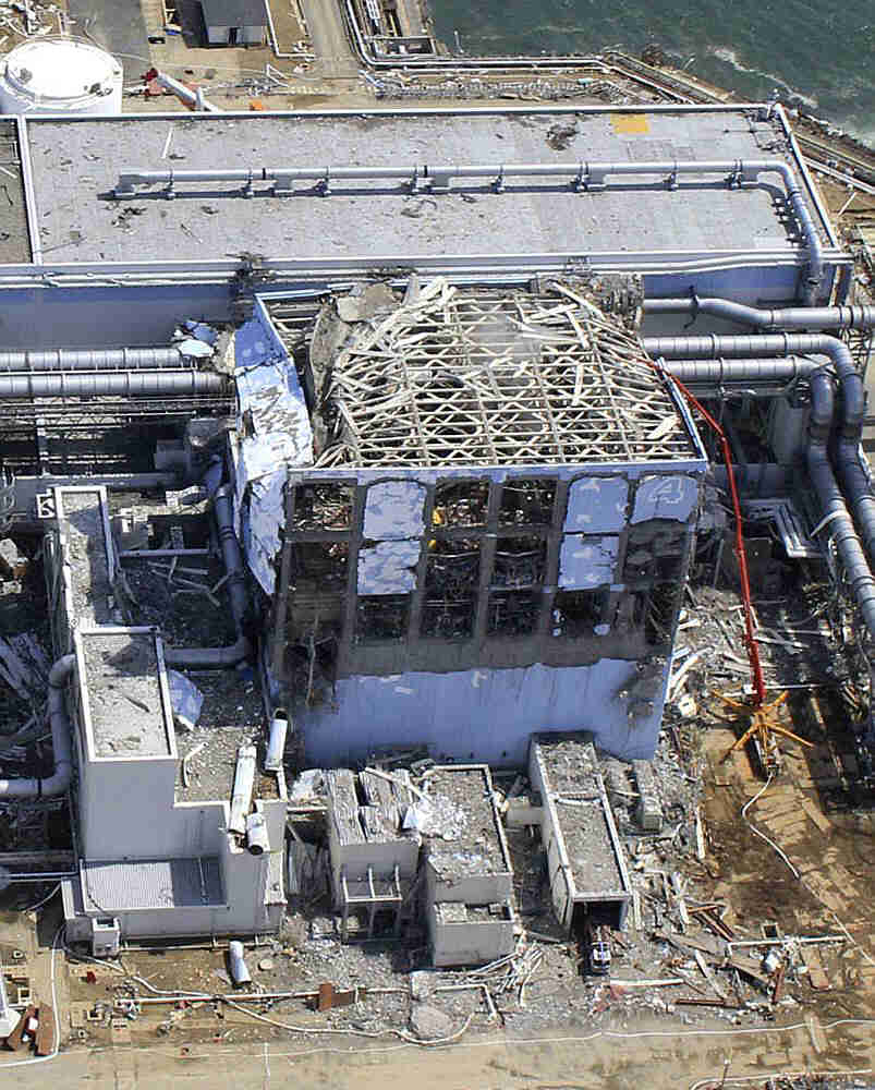
During the nuclear disaster in Fukushima , concrete pumps were used for various purposes: They stood outside three reactor buildings and with their "trunks" sprayed water through the destroyed roof into the cooling pool . In addition, a concrete pump sprayed diluted synthetic resin on various buildings to bind the radioactive dust there. The power plant operator called the devices "elephant" or "giraffe".
literature
- Main Association of the German Construction Industry (Hrsg.): Construction equipment list 2007 ; Bauverlag, Wiesbaden 2001, ISBN 978-3-7625-3619-2 .
Footnotes
- ↑ Today we say energy expenditure. So the aim was to achieve good energy efficiency .
- ↑ 101 meters: Concrete pump comes into the Guinness book building magazine from November 7, 2012. Accessed on March 27, 2018.
- ↑ Concrete pump in use on reactor block 4 ( Memento from May 28, 2011 on WebCite ). Air Photo Service Co. Ltd., Japan, March 24, 2011, archived from the original , retrieved May 29, 2011.
- ↑ Seismic Damage Information (the 95th Release) ( Memento from April 20, 2011 on WebCite ) (English, pdf). April 15, 2011, archived from the original ( Memento of the original from May 23, 2011 in the Internet Archive ) Info: The archive link was inserted automatically and has not yet been checked. Please check the original and archive link according to the instructions and then remove this notice. on April 20, 2011, accessed on April 20, 2011: protocol of the processes, u. a. also concrete pump inserts .
- ↑ Start of Spray of Dust Inhibitor to the Radioactive Materials around the Turbine Buildings and Reactor Buildings of Unit 1-4 of Fukushima Daiichi Nuclear Power Station ( Memento from May 26, 2011 on WebCite ). Tepco, May 26, 2011, archived from the original , retrieved May 26, 2011.
- ↑ Survey map of Fukushima Daiichi Nuclear Power Station as of 17:20 on April 23, 2011 ( Memento from April 30, 2011 on WebCite ) (English, pdf). March 23, 2011, archived from the original (PDF; 620 kB) on May 1, 2011, accessed on May 1, 2011: "concrete pumping vehicle called" Elephant "".
- ↑ Progress Status of “Roadmap towards Restoration from the Accident at Fukushima Daiichi Nuclear Power Station” ( Memento from May 22, 2011 on WebCite ) (English). Tepco, May 17, 2011, archiverg from the original (PDF; 109 kB), accessed on May 22, 2011.