
Precious metal contact motor rotary selector

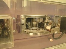
The precious metal contact motor rotary selector ( EMD selector ) is an electromechanical coupling element in analog telephone switching technology .
The EMD voter is a German development, it was developed by Siemens according to the specifications of the German Federal Post Office (DBP) and used in the German System 55 and System 55v. The EMD voter also became an export hit, for example to Italy, Luxembourg and other countries. In 1955, the DBP decided to only use the EMD voter in future in order to achieve a uniform technology. From 1955 onwards, new exchanges were only set up by various companies using this technology.
technology
In contrast to its predecessor, the lever-operated rotary selector (HDW), there is only one turning movement. This is driven by a special type of stepper motor, which consists of two coils . The voice wires are switched through via contacts coated with precious metal (palladium-silver alloy), which are electromagnetically actuated and pressed against the segment contacts arranged in a semicircle around the selector. This avoids a galvanic connection with the lines connected to the “multiple” during the dialing process, so that, in contrast to the HDW selector, neither cracking noises are caused in neighboring lines nor abrasion of the precious metal coating on the switching arms for the speech wires occurs.
Due to the type of drive, it can also move more switch arms than the lever-operated rotary selector (three switch arms on the lever-operated rotary selector, up to eight switch arms on the EMD). The eight switching arms arose from the requirement to connect the long-distance line with four wires. It is purely a rotary selector, the decades of the contact field are no longer one above the other as with a lever-operated rotary selector, but are all arranged in a semicircle on one level. This allows him to reach a very high walking pace while running. The speech wires are lifted when turning, these are only pressed against the slats when required by a pressure magnet. It was therefore possible to use noble metals for a very high quality in the speech veins. Due to its smooth running and the precious metal contacts in the speaking circuit, the EMD generates much less interference from vibrations on the neighboring voters. Another advantage of the pressure magnet: The sensitive contacts are not worn by grinding when turning. The wear and tear is significantly lower and the contact resistance is lower, which leads to good speech communication.
During development, attention was also paid to installation and maintenance.
- The EMD selector does not have to be adjusted during installation, so it can be installed and removed very quickly.
- The multiple of the voter is a solderless construction. This speeds up the construction of a frame. There is no danger of cold solder joints occurring .
The EMD selector can be controlled directly like a lever dial, which is then called direct control. It can also be controlled via a register and a marker (indirect control).
In the 1955 technology, the voter is controlled by a relay set arranged next to it and the pulse dialing process. The multi-frequency dialing method cannot be used with this direct control.
Depending on the transmission method, there are different designs, two with four arms for two-wire transmission in the local network or two with eight arms for four-wire transmission in the long-distance network. In telecommunication technology, indirect control by means of a corrector is common, since the use of cross lines means that the line can no longer be directly assigned to the selected digit.
Advantages over the rotary dial were the low noise voltage in the speech circuit, the high walking speed and the larger number of switching arms, which for the first time allowed a four-wire connection of the speech circuits in the exchange. Maintenance was easier, there was less wear and tear and the operating noise was much quieter.
Since the temperature in the non-air-conditioned operating rooms was subject to seasonal fluctuations, the walking speed might have to be corrected by additional lubrication or by mechanical adjustment of certain contacts if this was outside the tolerance ranges. Exceeding or falling below the target speed led to the wrong choice.
For all manual tests, measurements and settings on the contacts, the voter was inserted into the official doctrine , with which the contact segment in which the voter is located during operation was simulated.
Numerous EMD exchanges were equipped with an automatic test device with which the voters and relay circuits were routinely subjected to a functional test at night in times of low traffic. Corresponding messages with code numbers were printed for voters with disruptions or tolerance violations, which accelerated the elimination of interference.
Use in local exchange

Local traffic was structured hierarchically. A distinction was made between the stages:
- Call seeker (AS), call seeker basic traffic (ASg), top call seeker (SpAS)
- Changeover group selector (UGW) at partial exchanges
- I. Group voter (I. GW)
- II. To VI. Group voter (II. - VI. GW)
- Line selector (LW) and the
- Local exchange group selector (OGW) for incoming long-distance calls.
Even with HDW technology, each participant had their own selection, which immediately looked for a free line (a free group dialer) when they picked up the phone. If he didn't find any, he switched the busy tone to the intercom lines. It was the other way around with the caller. Up to 100 terminals were connected to a group of call seekers. The number of call seekers connected to a group was based on the traffic volume of the connected terminal equipment. This meant that the EMD system was more flexible to adapt to the volume of traffic than the HDW system. If one participant picked up his phone, the next free call finder in the group looked for the marked subscriber connection and switched the line through. Each AS was permanently connected to a group voter. The group voter signaled his readiness by applying the dial tone to the voice lines. If no AS in the group was free, the connection remained silent. In this case, no busy tone was created.
The I. GW processed the first digit dialed and switched on the corresponding II. GW group depending on the number dialed. So it went on to the III. GW etc., depending on the size of the local network and thus the length of the numbers in the local network. In the last step there was the line selector, to whose output up to 100 participants were connected and which processed the last two digits of the number.
For incoming long-distance calls , the OGW replaced the I. GW.
Use in long-distance transport

In domestic long-distance traffic, which was also hierarchically structured, voters were named as follows depending on their position in the long-distance telephone connection chain (see also: switching center ):
- Direction selector (RW). It was reached by dialing the first "0" of the area code, the so-called traffic elimination number (VAZ) from the 1st GW of the local exchange. The RW then established the first part of the long-distance connection. The RW received the information from a register that was activated while the connection was being established. The register also had the task of temporarily storing the incoming dialing impulses and, for the remote connection, correcting them exactly after "impulse" and "pause" to establish the remote connection. In larger exchanges, a two-stage arrangement of directional selectors could also be used.
- This next voter was usually a central exchange group voter (ZGW) at the top level . He in turn switched with the first digit of the area code, ie the first digit after the "0", the second section of the long-distance connection to the desired central exchange (for example 6: Frankfurt)
- Main exchange group selector (HGW) through. This was used to select the desired main exchange (for example 62: Mannheim) with the second digit of the area code (after the zero) in the third section of the connection.
- The connection met the node-switching center group selector (KGW) there. With the third digit of the area code, this established the connection to the desired exchange switching center (for example 626: Mosbach).
- There the local exchange group selector took over and established the connection to the desired local exchange (e.g. 6262: Aglasterhausen) with the fourth digit of the area code.
- The last link in the long distance connection was the local exchange group selector (OGW). In terms of circuitry, it was located in the "target" local exchange (Aglasterhausen), so to speak parallel to the first group dialer of this exchange, and processed (like the 1st GW for local calls) the first digit of the subscriber number.
This long-distance connection described was the longest possible because all voters in the hierarchy were involved in it. It was therefore called the key figure path . In the case of a long-distance connection, the first three digits of the area code were saved first, and the central corrector then determined the direction for the direction selector. The attempt was always made to use the shortest route (called cross route, QVL = cross connection line).
RW, ZGW, HGW, KGW and to some extent also the EGW were designed as eight-armed EMD selectors because they had to switch through the four-wire line sections of the long-distance connection equipped with amplifiers. The long-distance connection was four-wire because amplifiers could only amplify the conversation in one direction. As a result, the four-wire connection path in the direction of the destination was referred to as the “going” and “coming” part of the line. For example, if a directional part was disrupted due to amplifier failure, this led to the disruption feature "one-way communication".
According to international regulations of the CCITT , subscriber number, consisting of country code, area code (without the first 0) and telephone number, could have a maximum of twelve digits. For this reason, the central exchanges with usually very large local networks had shortened area codes (for example Frankfurt “0” 69), because the other maximum eight digits were required for the long subscriber numbers there.
Use of technology
In the Federal Republic of Germany , these voters were used in the switching centers of Deutsche Telekom from around 1955 until they were fully digitized . The last EMD voter exchange of Deutsche Telekom AG was decommissioned on December 17, 1997 in Stolberg-Gressenich . At the Deutsche Post of the GDR , motor rotary selectors of the System 58 similar to the EMD voters were used to a small extent. Meanwhile, the digitization of the news network has made this technology obsolete and EMD voters are no longer used.

At Deutsche Bahn there was an active EMD office in their own " BASA network" until 2005 . It was the last office of its kind in operation in Germany.
Individual evidence
- ↑ A multiple connects the contacts of the same importance when using several voters
- ^ Horst Woller, Kurt Sobotta: Modern telephony switching technology. Telekosmos-Verlag Franckh'sche Verlagshandlung, Stuttgart 1968, p. 164.
Web links
- Telecommunication Museum Aachen
- Telecommunication Museum Dresden (IGHFt eV)
- The EMD voter and his story with pictures
- Motor selector system 58 of the Deutsche Post (GDR)
- Dialing system 55 with EMD dialers - technical description
- Remote dialing system of the DBP with EMD - technical description
- Short video - EMD voters in action