Centrifugal separator
Centrifugal separators , sometimes also called cyclone , cyclone separator , cyclone filter or vortex , are used as mass force separators in technical systems for separating solid or liquid particles contained in gases (e.g. for exhaust gas cleaning). Centrifugal forces are used as the separation mechanism, which are created by creating a vortex flow. Hydrocyclones are used to separate emulsions and suspensions .
Demarcation
Differentiation from the centrifuge
Both centrifugal separators and centrifuges use the centrifugal forces acting on the respective contents of the apparatus to separate substances. While in a centrifuge the necessary kinetic energy is transferred to the medium to be separated by the rotational movement of the container, in the centrifugal separator the gases as carriers of the particles to be separated are set in a rotary movement by their own flow speed and corresponding structural design of the separator. The material is separated in the centrifuge through differences in density, in the centrifugal separator through the particle mass.
Differentiation from other inertia separators
As with gravity or inertial separators , centrifugal separators use mass-proportional field forces for particle separation. The effective forces in the aforementioned separators are essentially gravity or the force of inertia .
construction
Common outside diameters of centrifugal separators range between 20 cm and 6 m. The particle-laden gas can be fed to the rotationally symmetrical separator chamber tangentially (tangential cyclone separator) or axially (axial separator). With both types of construction, the particles are transported to the wall of the separation chamber.
Tangential cyclone separator
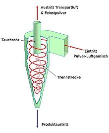
A tangential cyclone separator essentially consists of four parts: the inlet cylinder (top), the cone (middle), the particle collection container ( bunker , below) and the immersion pipe (attached in the middle from above down in the inlet cylinder).
The gas / particle mixture or liquid / particle mixture is blown in tangentially in the inlet cylinder and brought onto a circular path. Due to the tapering of the adjoining cone, the speed of rotation increases to such an extent that the particles are thrown against the walls of the cone by centrifugal force and decelerated to such an extent that they detach from the flow and trickle down into the collecting container. The cone is not absolutely necessary for heavy particles. The cleaned gas or the liquid leaves the cone through the central immersion tube upwards.
The guidance of the mixture can be strengthened by means of baffles attached to the inner wall of the separator in a spiral shape. In order to avoid that the vortex tears out particles from the hopper again, the transition from the cone to the bunker often in addition by a property in the middle Apexkegel ( apex is Latin for "top") is closed, so that only an annular slot between the plug wall and Apexkegel remains through which the particles get into the bunker.
The bunker can be emptied during operation, with the discharge taking place via a rotary valve to avoid gas exchange with the environment .
Axial separator
In axial separators, the swirl is mostly generated by guide vanes. The immersion tube is located opposite the gas inlet. The separated particles reach a collecting container through an annular gap between the separator wall and the immersion tube.
In contrast to the tangential cyclone separator, the flow direction is not reversed with the axial separator. The degree of separation and pressure loss are lower with the axial separator.
Multicyclone
Since it does not make sense to use a correspondingly large cyclone for larger exhaust gas flows, several smaller cyclones connected in parallel are combined in one housing to form a multi-cyclone in such cases. Axial separators are usually used to operate multi-cyclones. These can consist of up to several hundred individual separators.
Areas of application
Using a centrifugal separator, simple dedusting can be done with relatively little effort. It has long been known in industry for its robust, low-maintenance design. The insert extends over a wide pressure range from 0.01 bar to 100 bar and temperatures up to 1000 ° C . Because of the only moderate dust separation performance for the finest particles compared to other processes , it is often used as a pre-separator, for example in crematoria . Cyclones are often used as droplet separators behind gas washers .
The centrifugal separators, known as “vortexes” or “cyclones” in a blast furnace system, are, for example, an intermediate element for finer coarse dedusting of the top gas, downstream of the simpler dust bag and upstream of the electrostatic filter.
Working cyclones are also used to separate water from live steam between the steam generator and turbine in steam power plants and nuclear power plants or to separate condensate in gas coolers .
In analysis technology, cyclones are used as sample gas coolers. There, condensate introduced and condensate / droplets formed by cooling (for drying) should be separated from the gas flow.
The determination of fine dust fractions in accordance with the EN 481 standard or the Johannesburg Convention can be carried out using centrifugal separators.
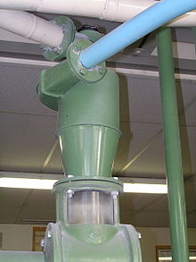
Centrifugal separators are used in mills to remove dust from the aspiration air. All larger machines are vacuumed in mills, as flour dust can be a health hazard (flour asthma) and represents a great risk of a dust explosion .

In motor vehicles with internal combustion engines that often work in a dusty environment (such as agricultural machinery or off-road vehicles ), a centrifugal separator is used as a pre-separator in front of the actual air filter . The so-called cyclone filter removes dust and water and thus relieves the actual air filter. This leads to a significant increase in the service life of the air filter.
Older vacuum cleaners and modern industrial vacuum cleaners (all-purpose vacuum cleaners ) also work on the cyclone principle. They only have a cylindrical container with a tangential inlet in which solids and water collect. The immersion tube is often provided with a particle filter and in some cases has a float valve to protect the suction fan from water when the container is full. In older vacuum cleaners, the particle filter was a textile part on which the fine dust collected on the outside. Cylindrical filter cassettes are used today.
In 1985 James Dyson developed a bagless household vacuum cleaner based on the cyclone separator principle. The further developments based on the basic model are sold under his family name. However, there is the problem of inadequate separation of fine dust with these, which is why vacuum cleaners based on this functional principle usually also have a final filter .
literature
- Friedrich Löffler : Dust separation. Georg Thieme, Stuttgart et al. 1988, ISBN 3-13-712201-5 .
- VDI 3676: 1999-09 Inertial Separators. Beuth Verlag, Berlin. ( Summary and table of contents online )
Web links
Individual evidence
- ^ A b c Franz Joseph Dreyhaupt (Ed.): VDI-Lexikon Umwelttechnik. VDI-Verlag Düsseldorf, 1994, ISBN 3-18-400891-6 , pp. 497-498.
- ↑ Frieder Schuh (Red.): Encyclopedia of natural science and technology. Volume 5. Verlag Moderne Industrie, Munich 1981, ISBN 3-478-41910-7 , p. 5227.
- ↑ VDI 3676: 1999-09 Inertial Separators. Beuth Verlag, Berlin, p. 12.
- ^ Franz Joseph Dreyhaupt (ed.): VDI-Lexikon Umwelttechnik. VDI-Verlag Düsseldorf, 1994, ISBN 3-18-400891-6 , p. 792.
- ↑ Matthias Stieß: Mechanical process engineering. Volume 2. Springer, Berlin et al. 1994, ISBN 3-540-55852-7 , Section 7.2.3.1, excerpts online from Google Books .
- ↑ VDI 3459 sheet 7: 2018-09 Terminology in energy and waste management; Exhaust gas treatment. Beuth Verlag, Berlin, p. 7.
- ↑ VDI 3460 sheet 1 : 2014-02 emission reduction; Thermal waste treatment; Basics (Emission control; Thermal waste treatment; Fundamentals). Beuth Verlag, Berlin, p. 94.
- ↑ Walter Barth: Limits and possibilities of mechanical dedusting. In: dust . 23, No. 3, 1963, pp. 176-180.
- ↑ Harald Pfaller, Heinz-Uwe Riedel, Clemens Marb: Exhaust emissions from thermal systems: From standstill to transient to (quasi) stationary operation. In: Hazardous substances - cleanliness. Air . 70, No. 5, 2010, ISSN 0949-8036 , pp. 188-196.
- ↑ VDI 3679 Part 3: 2010-6 wet separator; Droplet eliminators (wet separators; mist eliminators). Beuth Verlag, Berlin. P. 36.
- ↑ Hans Schoppa: What the blast furnace operator must know about his work (= Stahleisen-Schriften. Vol. 5). 4th, revised edition. Stahleisen, Düsseldorf 1992, ISBN 3-514-00443-9 .
- ↑ Heinrich Thürmer, Horst Bytel, Erhardt Gierke: The transition from the Johannesburg Convention to DIN EN 481 - gravimetric comparison measurements at workplaces. In: Hazardous substances - cleanliness. Air. 62, No. 11/12, 2002, ISSN 0949-8036 , pp. 447-454.


