Group delay
Under the group delay ( English group delay ) of narrow-band signal by an LTI system (eg., By an electronic filter or a transmission channel ) is the delay of the envelope of this signal.
Illustration and meaning
The right figure shows a wave group before or after passing through an LZI system (hereinafter referred to as “system”) such as B. an electronic filter or a transmission link . The so-called envelope is shown as a blue dashed line, the carrier frequency in purple and the group delay between the input and output signal with . The group delay correlates with the time offset of the envelope.
The transit time of a wave group through a system depends on the properties of the system and on the carrier frequency of the wave group. The group delay often has a non-linear dependence on the frequency. However, if the group delay is constant, the transit time of different wave groups at different frequencies is the same. I.e. When passing the system, all wave groups experience the same delay, which is why the relative position of the groups to one another is retained. For this reason, a broadband signal does not “dissolve” when passing through such a system. Based on optical physics, there is virtually no dispersion .
If a system has a linear phase response , then it has a constant group delay.
A constant group delay is e.g. B. desired for transmission links so that the phase profile of a useful signal to be transmitted is preserved as possible during transmission. The transfer function of a coaxial cable , for example, has, to a good approximation, a linear phase response and thus a constant group delay.
definition
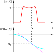
The system should be based on a transfer function with magnitude frequency response and phase response , so that:
Or.:
The group delay results from the phase response through:
With a given transfer function in the Laplace image range , the group delay can also be calculated directly (without going through the phase representation):
Mathematical description
To derive the group delay one studies the response of a system to the excitation with a signal in the form of a wave group. The stimulating signal, like the response of the system, should be real, i.e. not complex. The wave group can be described as the product of a real envelope with a real harmonic fixed frequency ( carrier frequency ):
The associated amplitude density spectrum is
The magnitude frequency response of the envelope should be limited to a sufficiently small frequency range and should disappear quickly enough outside this range. In this context, sufficiently small and fast means that the magnitude frequency response of the transfer function or the phase response in the areas and can be approximated sufficiently well by linear functions.
For systems with a real impulse response , the magnitude frequency response is an even function in . In the areas around, the following applies approximately:
For systems with a real impulse response , the phase is an odd function in . In the areas around, the following applies approximately:
The constants and are obtained by the Taylor expansion of the phase response . Concretely applies .
By applying the transfer function in the frequency domain to the wave group and by Fourier inverse transformation under the given conditions, the answer is obtained at the output of the system:
You can see from the argument of the envelope that it is related to the runtime of the group. With the definition of the group delay
one identifies . The envelope of the group is thus delayed by exactly one group delay after passing the system.
The group delay is to be distinguished from the phase delay. In this example the phase delay is:
Examples
First order low pass
The group delay of a low-pass filter (linear continuous system of the first order) should be specified. This system can be implemented as an RC element , for example. From the frequency response
the phase response results in:
Here is a filter-dependent constant. The group delay for this low-pass filter results from:
Acoustics
A group delay that is as frequency-independent as possible is also important in electro-acoustics , in particular for realistic sound reproduction. Many components of an audio playback chain, such as the loudspeaker crossovers ( crossover ), change the group delay of the signal. But the architecture of listening rooms also has a significant influence here. Acoustic resonators can influence the group delay just like components of loudspeaker systems. It is important to know the perception threshold for the audibility of group delay changes as a function of frequency, especially if the audio chain is intended for Hi-Fi playback. Tables can be found at Blauert and Laws:
| frequency | Audibility threshold |
|---|---|
| 500 Hz | 3.2 ms |
| 1 kHz | 2 ms |
| 2 kHz | 1 ms |
| 4 kHz | 1.5 ms |
| 8 kHz | 2 ms |
literature
- Athanasios Papoulis: The Fourier Integral and Its Applications. McGraw-Hill, New York [et. a.] 1962, ISBN 0-07-048447-3 (also published without ISBN).
- Karl-Dirk Kammeyer: message transmission. 3. Edition. Teubner Verlag, Leipzig Wiesbaden 2004, ISBN 3-519-26142-1 .
- Norbert Fliege: Systems Theory. Teubner Verlag, Stuttgart 1982, ISBN 3-519-06140-6 .
Web links
Individual evidence
- ^ Blauert, J. and Laws, P .: "Group Delay Distortions in Electroacoustical Systems", Journal of the Acoustical Society of America, Volume 63, Number 5, pp. 1478-1483, May 1978


![\ tau _ {{{\ mathrm {gr}}}} (\ omega) = - {\ frac {d} {d \ omega}} \ left [- \ arctan \ left ({\ frac {\ omega} {\ omega _ {{3 {\ mathrm {dB}}}}}} \ right) \ right] = {\ frac {1} {\ omega _ {{3 {\ mathrm {dB}}}}}} {\ frac {1} {1 + ({\ frac {\ omega} {\ omega _ {{3 {\ mathrm {dB}}}}}}) ^ {2}}}](https://wikimedia.org/api/rest_v1/media/math/render/svg/330f4be40f45281840a5fd327395b93aa20df76b)