
Typewriter ball head

The typewriter ball head (more rarely: type head ) is a compact type carrier in spherical shape used in electrically powered typewriters . The written characters are in a plurality of superimposed circles on the circumference of a ball ring disposed. To select a character, the head is rotated around the ring axis and tilted between the type circles. Each key triggers the selection movements for the corresponding type. To print, the very light ball head is hit against the platen with the stretched paper and the ribbon over it .
The ball head was introduced in the IBM Selectric typewriter on July 31, 1961.
The ball head was ultimately replaced by the modern type wheel , the only rotational movement of which could be generated by the light electric motor moving in the direction of the line. The complex mechanisms for rotating and tilting the ball head were no longer necessary. The type wheel is lighter than a ball head, which also contributes to even faster writing and printing in connection with typewriters and text systems.
Differentiation from other type carriers
The ball head is a type carrier containing all types used. It was developed from the short type cylinder used by Blickensderfer for the first time in 1893 (then called a type wheel ) for an IBM typewriter presented in 1961. Essential features of a toy typewriter manufactured by Louis Marx and Company were used. To select the desired type, a rotation and vertical displacement are required for the type cylinder, for the ball head rotation and tilting (called tilting by some authors) and for the more modern type wheel only one rotation. These three type carriers have the advantage over type levers on type lever typewriters that they can be quickly exchanged as a compact component in order to enable a change to a different font - e. B. for writing special characters. The fact that a “ secretary's dream ” (IBM advertisement) came true because no typing levers got stuck when typing quickly was nothing new. In addition to the Blickensderfer , this dream had already been fulfilled in other older, albeit slower typewriters with compact type carriers.
Function of the IBM ball head

In the IBM typewriter with ball head, the relatively light ball head was moved in the line direction instead of the platen for the first time.
The print types are arranged on four circles on the surface of the spherical ring - comparable to circles of latitude on the globe. By tilting the head about an axis running parallel to the platen through the center of the sphere, the circle with the desired print type is selected. By turning around the ball axis, the desired type is determined within this circle, it is now in the correct position near the point of impact on the paper. Types lying next to one another on a circle are offset by an angle of rotation of 18 ° for a maximum of 20 types per circle; instead of 80 possible types, IBM also had ball heads with 88 (see photo above: ball head with 22 points on the lower edge) and 96 types in the range, which requires smaller angles of rotation. The type that can be reached with the help of the Shift key is each offset by 180 ° on the same circle. Pressing the shift key first causes a half turn of the ball head, which is followed by the turn corresponding to the selected type. Frequently used types are arranged close to one another in order to minimize rotational movements.
The mechanism for the detachable connection and a handle are located in the cap of the replaceable ball head. The serrated ring on the lower edge is used for fine adjustment after turning around the spherical head axis. An IBM -Kugelkopf mm has a total height of 27 mm (teeth tips to cap), and an outer diameter of about 35 and weighs 10.2 g.
Drive of the ball head in IBM typewriters

If in most typewriters the carriage with the platen and the clamped writing sheet moves horizontally to reach the next writing position - within the same line - then in IBM ball-head typewriters the roller with paper stops and the ball head moves to the desired position in front of the sheet pushed. For this purpose, it is mounted on a slide that is pushed back and forth by a motor over a wire rope. In order to select the desired print type, the ball head must be rotated and tilted accordingly, and suddenly pressed against the platen to trigger the writing process. All these movements are triggered by a single electric motor fastened in the machine frame after being released by pressing the appropriate button.
The ball head slide is moved back and forth with a wire traction mechanism , on one strand of which it is attached. The ball head rotations are generated with the help of movements of one pulley each in two additional traction drives. The wire ropes of these gears, which are moved with the ball head slide, are cut open. One of the rope ends is firmly attached to the slide, the other to a lever that causes the corresponding ball head rotation on the slide. By deflecting a pulley, the free end of the rope pulls the lever and rotates or tilts the ball head, depending on the selected type of pressure. The selection process is independent of the current position of the ball head slide and can also take place during a slide movement.
Olivetti
The Olivetti company dispensed with the elaborate wire gears in its ball-head typewriter, which could be built after the expiry of IBM patents, and stayed with the usual typewriter trolley with transverse movement of the platen as with the model machine Blickensderfer No. 5.
details
In the following, some details of the method of operation described above are explained in more detail with the aid of schematic diagrams. The description is based on the original concept from IBM. In the course of development, mechanical functional principles have been changed many times and increasingly replaced by electromechanical or electrical-electronic components.

Movement of the ball head

Inclination of the ball head

Rotation of the ball head

Universal joint of the ball head

Locking of the ball head

Complete ball head
There are four basic movements required to achieve printing. On the one hand, a relative movement of a carrier (with support tube and spherical head) along a path parallel to the platen axis S is required. The platen can be stationary and the carrier can be moved (IBM) or the opposite variant is used. The support tube can be pivoted about an axis on the carrier, which also runs parallel to the platen axis, so that the ball head can hit the platen when it is pressed. In order to be able to select a certain type of printing, the spherical head can be inclined about an axis B running through its center point and again parallel to the platen axis (selection of the “latitude”). The "degree of longitude" is determined by rotating the spherical head around this inclined "polar axis" C. Since the inclination and rotation of the spherical head run simultaneously and without mutual interference, quick access to the type to be printed is guaranteed. The simultaneous movements lead to the "dancing" of the ball head.
The support tube carries the inclination block in a fork, which can be inclined about an axis defined by two pins. A section of a bevel gear is attached to the incline block and meshes with a bevel gear attached to the incline shaft. The inclination shaft is mounted in the support tube. Rotating the inclination shaft by a certain amount leads to a defined inclination of the inclination block.
The ball head holder is rotatably mounted in the inclination block. The ball head (open at the bottom) is attached to this in a defined position with the aid of a latching mechanism (not shown). The inclination shaft is designed as a hollow shaft in which the rotating shaft can move. The rotary shaft and ball head holder are provided with universal joints ( cardan joints ) which are connected by a connecting piece to form a double universal joint . This ensures a uniform transmission of the rotary motion of the rotary shaft to the ball head holder even when the inclination block is inclined. The two connected balls of the universal joints with elongated holes (closed or open) are referred to in technical jargon as dog bones. Alternatively, a differential gear can be used for the rotary movement .
For the respective pressure positions of the ball head, positioning aids are provided which are released again when the two shafts are rotated by their torques. These locking aids are effective between the inclination block and fork / support tube or inclination block and ball head. For example, a ball that can move against a spring in the inclination block is pressed into dome-shaped recesses on the “equator” on the inner wall of the ball head (according to the positions of the types) (securing the rotational position). The inclination position is secured in a very similar way in that a resilient ball arranged in the fork (or the support tube) engages in a toothed locking piece attached to the inclination block. In later versions, no domes or balls were used. The open edge of the ball head was serrated. Levers that were controlled by a special actuator (see below) engaged in the inclination locking piece and the spherical head teeth, so that the inclination and rotating shaft did not have to apply the torque to release the locking.

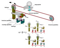
Rotation and inclination of the ball head with a traction device (wire rope, steel band)

Inclination of the ball head with a dial wire and dials

Rotation of the ball head with a dial wire and dials
The tilting and rotating shafts are rotated with traction means (wire ropes, steel straps). The principle is the same for inclination and rotation. The two shafts are each provided with a pulley to which one end of the traction mechanism is attached. The pulleys are twisted in one direction by spring forces so that the traction mechanism is tensioned. The other end of the traction mechanism is attached to the carriage carrying the ball head. The carriage is also moved with wire ropes, but these are not shown in the pictures. The rope is guided over three stationary sheaves. The displaceable pulley 4 should also initially be assumed to be stationary in order to illustrate the independence of the movement of the inclination and rotary shaft from the carriage movement. It can thus be seen that the displacement of the carriage does not result in any twisting of the inclination or rotating shaft. The rotation of these two shafts (and thus the selection of the type to be printed) is done with a dial wire guided over dials. The pulley 4 moves linearly as a function of the movement of the dials. The rope is pulled off the respective sheave for inclination or rotation against the spring force, or it is wound onto the pulley by the spring force. A (defined) movement of the dials thus leads to a (defined) movement of the shafts moving the ball head. Two dials are required for tilt and six for rotation. This is explained as follows.
Inclination: The starting position of the ball head for the inclination is the upper type circle (no adjustment of the two dials). A rotation of the inclination shaft by an adjustment unit (certain angle) brings the next type circle into the printing position. In order to be able to use types of all four circles, on the one hand the dials do not have to be moved (first type circle) or on the other hand they have to be shifted up or down in such a way that three different adjustments result. This is achieved in that, when the first dial is activated, it moves by an amount corresponding to an adjustment unit of the inclination shaft and activates the second (without activating the first) two adjustment units. If both dials are activated, the total is three adjustment units. A corresponding code table is inserted in the picture. The adjustment of the dials is explained below.
Rotation: The starting position for the rotation is the middle column (in the case of eleven columns, the sixth column) of the small letters. When activated, the dials 5 and 6 cause the spherical head to rotate 180 ° when activated (by pressing the toggle key on the typewriter in a manner not shown) and thus bring the capital letters (also 11 columns) into the starting position in front of the platen. When activated, the dials 1 to 4 are adjusted by different amounts with different signs, each corresponding to a certain number of adjustment units (VE) of the rotary shaft. A suitable combination (addition) of these amounts ensures that the rotating shaft (and thus the ball head) can be adjusted from the starting position by five positions (columns) in one direction and another five positions in the opposite direction. A corresponding code table is given in the picture. With a total of 22 columns, one adjustment unit corresponds to a rotation of the rotary shaft by 16.36 °.
Lever system (Whiffletree) for tilting the ball head
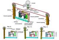
Lever system (Whiffletree) for turning the ball head
An alternative to the type selection with dials is the use of "calculating" lever systems (Whippletrees or Whiffletrees). The dials and the dial wire are no longer necessary and the remaining traction device is only guided over two pulleys. These are mounted in pivotable levers (only one lever is required to adjust the inclination). The vertically movable selector fingers can all be adjusted by the same amount (with the same sign) and thus only have the states "activated" (1) and "not activated" (0). The lever system for the inclination (four positions) manages with two selector fingers, which are connected by a lever with the ratio 1/3 to 2/3. The spring force acting on the angle lever always tries to pull the selector fingers against their stops. When activated, they are pulled away from the stops. A more complicated system is required for the rotation. There are three selection fingers and an additional positioning finger. The spring-loaded control lever pulls the angle lever and the support pin fastened in it via the connecting rod against a semicircular recess in the connecting lever. This can rotate around a pin fastened in the positioning finger depending on the selected fingers that are activated. The angle lever follows this movement, since the contact pin is constantly pressed against the connecting lever by the spring force and thus brings about the desired adjustment of the adjusting lever via the connecting rod. The traction mechanism is withdrawn from the pulley of the rotating shaft by the corresponding adjustment units. In this way, however, only the starting position of the rotation and another five columns in the positive direction can be realized. In order to be able to cover the negative positions (traction device is wound onto the pulley of the rotating shaft), the positioning finger can be moved vertically. As a result, when the dial fingers are activated, the desired five negative positions result, depending on the combination. This is illustrated in the picture for positions +3 and -3. The dials 5 and 6 for rotating the ball head by 180 ° are also omitted in this variant. This rotation is realized by pivoting the switch lever, which is done by pressing the switch button in a manner not described here. In contrast to the schematic illustrations, the Whiffletrees are designed as thin sheet metal parts.
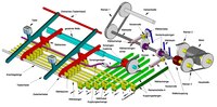
Principle of a ball-head typewriter

Triggering a printing process

Printing a character (pressing force by cams)

Printing a sign (pressure force by spring)
The key levers are arranged next to each other as usual (only two shown) and rotatable about a common axis. Each key lever is assigned an intermediate lever which has selector prongs, the combination of which corresponds to the type to be printed. On the prongs there are selector tabs which, like a selector lever, are attached to selector rods. Spring forces cause the selector tabs to rest against the selector prongs and the selector levers to be in a certain starting position. When a key lever is depressed, the corresponding intermediate lever is also pushed downwards, rotating around the stop rod. The intermediate lever presses on the coupling rocker, which is mounted in two rocker arm bearings (only one shown), and swivels it. The coupling rocker acts (in a manner not shown) on the rocker coupling ( wrap spring coupling ) so that the belt pulley A, which is constantly driven by the motor via the belt 2 and rotates loosely on the cylindrical extension of the (stationary) toothed shaft, is coupled to the latter and set the wave in motion. A tooth of the toothed shaft grips the depressed intermediate lever and moves it, with its elongated hole moving on the stop rod. The (selected) selector tabs are also shifted and turn the selector rods about their axes, with the corresponding selector levers being pivoted as well. All of the unselected intermediate levers are not affected by this, since the respective selection tabs move in the spaces between the prongs. The rotation of the selector rods leads to the fact that coupling rods are shifted (only coupling rod 1 is shown in the side view), which couple the cam clutches (also wrap spring clutches) and their cams (cam disks) located on the (resting) selector shaft in a manner not shown on the selector shaft (only two couplings and cams shown).
The swing clutch is designed in such a way that the toothed shaft only rotates through 120 ° and then the belt pulley A is decoupled again. The tooth of the toothed shaft has then passed the intermediate lever and this is pulled back into its starting position by spring force (just like the key lever). This has no effect on the cam clutches, since once selected they only disengage after one revolution of the selector shaft. Only then do the coupling rods, the selector levers and thus the selector rods with their selector tabs also reset.
All intermediate levers have a selector prong for the coupling rod 1. So this is always selected. While the coupling rods 2 to 7 act on the cam couplings, the coupling rod 1 switches the shaft coupling (wrap spring coupling) somewhat delayed compared to switching the cam couplings (all cams are then already connected to the selector shaft). The shaft coupling connects the main shaft, which is constantly driven by the engine by the belt 3, with the selector shaft, so that the selected cams now rotate. The selector shaft with its clutches and cams thus represents a switchable camshaft . The shaft coupling is designed in such a way that the selector shaft only rotates one revolution and is then uncoupled from the main shaft. Selector rockers with their cam rollers are resiliently pressed against the cams. The dials attached to the selector arms are thus adjusted when the cams are rotated. After rotating the cams by a certain angle, the dials 1 to 4 (rotation) and the two dials for the inclination have reached their target position (according to the code above) and the corresponding type has been selected on the ball head. The cams now have a constant radius for a certain angular range of their further rotation. As a result, the dials are no longer moved and the selected type stands motionless in front of the platen for a certain period of time. In this phase the printing is carried out. The remaining rotation of the cams up to the completion of a full revolution then returns the dials to their starting positions.
The dials 5 and 6 (180 ° rotation of the ball head) are also adjusted by a cam clutch (not shown) which moves two cams together and sits on the selector shaft, which is activated by the shift key.
Whiffletrees (Whippletrees) are adjusted in a similar way to the dials. All selector fingers are pressed down by a common lever that is actuated by a cam on the selector shaft. According to the respective character code, pull rods connected to the dialing fingers (comparable to the coupling rods described above) or pull ropes bring unselected fingers out of engagement so that they are not picked up by the lever and thus not depressed.
It should be mentioned that after the manual keystroke of a key, all further operations up to the point of printing are carried out automatically and are therefore independent of the force of the typing force. This ensures even pressure.
The carriage is guided by a guide rail, in the groove of which the guide nose of the carriage slides, and the square shaft, and is moved by cables (not shown). When the carriage is moved, both the pressure cam and the guide bushing, which both move with the carriage, slide on the square shaft. The guide bushing is rotatably mounted in the carriage so that the square shaft can turn. The ball head is mounted with the support tube on the pressure rocker, the rocker arm with its pressure cam roller is pressed against the pressure cam by spring force (spring not shown). The pressure rocker can be swiveled around two bearing bushes fixed in the carriage. The cables for the pulley of the inclination and the rotating shaft are passed through one of the bearing bushes (their other ends are attached to the carriage). As a result, they are only slightly twisted when the pressure rocker moves, because the sheaves are pivoted approximately around the contact points (contact points) of the cables. The square shaft is connected to the selector shaft by belt 1 (gear ratio 1: 1) and thus moves synchronously with it (one revolution). When the selector cams rotate, the pressure cam also rotates. This is designed in such a way that in the above-mentioned printing phase (constant radii of the selector cams) it swivels the pressure rocker briefly with its increase, whereby the ball head is hit against the platen to print a character. The compressive force is adjustable in a manner not shown here. It is also possible to apply the compressive force not by the cam but by the spring force. The pressure cam must be designed accordingly. The pressure force can then be adjusted simply by changing the spring force. An electromagnet can also be used for the pressure stop.
The time from hitting a key to completing the print is about a tenth of a second.

Control of the detent

Fixation of the tilt position of the ball head
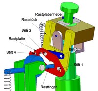
Locking plate for determining the rotary position

Locking the rotary position of the ball head
An alternative to the above-mentioned locking of the ball head provides a solution controlled by the selector shaft instead of resiliently pressed balls (passive locking). For this purpose, the guide bushing of the carriage rotating synchronously with the selector shaft is provided with a control groove in which a control lever engages. The control arm of an angle lever, which is mounted in a holder arranged on the pressure rocker, is applied to the control lever by spring force, so that it is pivoted depending on the movement of the control lever (or the guide bushing). The control groove is designed so that in the pressure phase determined by the selector shaft, the locking finger of the angle lever moves from its lower rest position in the direction of the ball head and a locking piece attached to the inclination block locks for the inclination. The jagged lower edge of the ball head is not caught by the locking finger.
Arranged on the locking piece is a locking plate lever which is rotatable about the pin 2 and around the pin 3 of which a locking plate can be moved. This is guided by the pin 1 seated in the locking piece in an elongated hole and is acted upon by a spring force acting on the pin 4. The locking finger protrudes through a recess in the locking plate into the teeth of the locking piece. In its starting position, the latching finger presses the latching plate down against its spring force so that it does not engage the ball head prongs. When the locking finger moves upwards and fixes the locking piece (inclination), the locking plate can move under the action of the spring force, the shift being defined by the locking plate lever and the elongated hole. In this position, the locking plate engages in the (non-radial) spherical head prongs and locks the rotary position of the head.
Trivia
In the film Mademoiselle Populaire , the main actor Louis invents the ball-head typewriter.
The typewriter IBM Selectric II was from October 1976 by the Soviet secret service to listen to the US Embassy in Moscow and the consulate in Leningrad bugged . Parts of the mechanical linkage were replaced by non-magnetic ones and small magnets were attached. These caused magnetic changes when writing and thus turning the ball head, which were registered and immediately transmitted by radio.
Web links
Notes and individual references
Attention! With DEPATISnet information, an error message often appears the first time it is clicked. The second time the link works.
- ↑ 50 years ago: IBM introduces Selectric ball-head typewriter, report at heise.de, July 31, 2011
- ↑ DEPATISnet | Document US000002287184A. Retrieved August 22, 2017 .
- ↑ DEPATISnet | Document US000003223220A. Retrieved August 23, 2017 .
- ↑ www.stb-betzwieser.de: Selection of historical typewriters with type cylinder or type wheel
- ↑ "Rotations of the IBM ball head" In the Computer Museum for Computer Science at the University of Stuttgart (with pictures and explanations)
- ↑ DEPATISnet | Document DE000001063612B. Retrieved August 22, 2017 .
- ↑ DEPATISnet | Document DE000001078591B. Retrieved August 22, 2017 .
- ↑ DEPATISnet | Document CH000000402013A. Retrieved August 23, 2017 .
- ↑ DEPATISnet | Document DE000001283856A. Retrieved August 23, 2017 .
- ↑ DEPATISnet | Document DE000002055924A. Retrieved August 23, 2017 .
- ^ IBM: Selectric Keyboard Printer. October 1, 1964, accessed August 23, 2017 .
- ↑ DEPATISnet | Document DE000001190958A. Retrieved August 23, 2017 .
- ↑ DEPATISnet | Document DE000001809831B. Retrieved August 23, 2017 .
- ↑ NSA website: Learning from the enemy - The Gunman Project ( Memento of the original from October 15, 2014 in the Internet Archive ) Info: The archive link has been inserted automatically and has not yet been checked. Please check the original and archive link according to the instructions and then remove this notice. , United States Cryptology History, Series VI, Volume 13, January 8, 2007 (English)
- ↑ Fabian A. Scherschel: Espionage: This is how the Soviets bugged typewriters , Heise online, July 14, 2014