Königsberg class (1927)
|
The Karlsruhe
|
||||||||||||||
|
||||||||||||||
|
||||||||||||||
|
||||||||||||||
|
||||||||||||||
The light cruisers of the Königsberg class , also known as the K-class or K-cruiser , are three cruisers of the German Reichsmarine and later the Kriegsmarine . They were named after German cities whose name begins with a "K". After the I. Königsberg class and the II. Königsberg class , this was the third class of the ships called "light cruisers" and no longer small cruisers . Projected a few years after the First World War under the conditions of the Versailles Treaty, the ships could only be used to a limited extent and were already considered obsolete when the Second World War broke out.
history
The class designed in the years 1924/25 under the responsibility of the naval chief construction officer Albrecht Ehrenberg still suffered from the restrictions of the Treaty of Versailles , which restricted cruisers to 6,000 tons of tonnage. Since the German designers made full use of and even exceeded this upper limit from the outset, there was no building reserve, which is otherwise common in warships and important for stability calculations, and which included the weight of later additions. At least the restriction to guns in single mounts, as with its predecessor Emden , could be relaxed, so that the installation of newly developed artillery towers was now guaranteed.
draft
The construction was based on the longitudinal frame-cross-band construction that has proven itself in torpedo boats . The ships had 16 watertight compartments and the double bottom extended over 72% of the total length. In order to comply with the tonnage restriction, 85% of the connections were welded instead of riveted to save weight. The lightweight construction, as it were enforced by the contract, led to high loads on the hull of the ship during shooting and in rough seas, so that there were repeated cracks at the joints of the welds. For example, in a hurricane during a Pacific voyage in 1936, the Karlsruhe ran the risk of breaking apart due to severe structural damage. In addition, the ships suffered from greater stability problems because of their large length-to-width ratio of over 11, which meant that they were only used in the North and Baltic Seas during World War II and not as planned in the trade war . Later, due to the lack of stability, the fuel bunkers were not allowed to be emptied below 680 m³, which ruled out overseas use from the outset.
drive
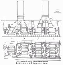
The ship had two shafts, each with a propeller made of iron bronze, which had a diameter of 4.1 m. The two electrically operated rowing machines could be operated by hand in an emergency. The mixed propulsion system was new: steam turbines for combat, diesel for cruising. The main propulsion system consisted of six oil-fired water-tube boilers, which were located in a total of four boiler rooms. Two boilers were connected to the front chimney and four boilers to the aft chimney. The four larger boilers each had 22 and the other two boilers each had 18 centrifugal atomizer burners, the operating pressure being 16 atmospheres . The steam generated acted on four independent turbine sets, two of which were connected to one of the two shafts by means of a gear transmission. This connection could be separated by a double claw coupling. The four turbine sets were divided into two main turbines and two marching turbines, with the reverse turbines being integrated in the latter. When the boilers were cold, an alarm could be triggered in an absolute emergency and in disregard of all safety regulations, which could bring the boiler to operating pressure within just a few minutes.
This so-called wet steam system was relatively large in terms of space and therefore took up half of the 16 departments, but it was much more reliable than the complicated and fragile smaller high-pressure superheated steam systems, which later led to persistent problems on the Admiral Hipper class and also with the destroyers 1934 should lead.
In addition to the main propulsion system, the three ships were equipped with a march diesel engine system during construction. This was actually not intended in terms of design, but these engines proved themselves so well on the test bench that they were retrofitted for reasons of the larger radius of action. These were two reversible four-stroke ten-cylinder engines with an individual output of 900 hp, which acted on the main shaft by means of a Vulcan clutch (oil-filled gearbox without speed reduction). With the engines an economical cruising speed of 10 knots could be achieved. The disadvantage was that the two propulsion systems could not be operated at the same time and the ship had to stop and shut down the engines to switch between the two modes of operation. This coupling process, which takes around 15 minutes, could be a major tactical disadvantage in an emergency.
In search of any weight savings, these motors were also manufactured in an extremely lightweight construction. This and the fact that there was actually no room for these engines on the ship led to initial difficulties, as a result of which the proponents of high-pressure superheated steam systems got the upper hand for a short time and the promising diesel engine drive was not pursued for a while.
| Mileage results using the example of Karlsruhe | |||
| date | January 16, 1930 | January 13, 1930 | January 15, 1930 |
| Duration | 6 hours | 6 hours | 3 hours. |
| speed | ~ 15 kn | ~ 25 kn | ~ 31 kn |
| Turbine circuit | both marching turbines | both main turbines | all four turbines in parallel |
| Shaft speed (1 / min) | 138 | 245 | 345 |
| Total shaft power ( WPs ) | 4,000 | 23,200 | 55,400 |
| Heating oil consumption per hour | ~ 11.6 t | ~ 17.6 t | ~ 35.3 t |
Armament
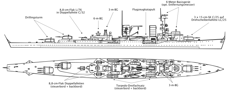
In order to save weight, it was decided in the Königsberg class to erect three treble towers instead of four twin towers - the first treble towers in the German Navy. One tower was forward and two aft. That meant that only a third of the firepower was directed straight forward. One reason for this setup was the task of reconnaissance, which was considered during the construction, as more firepower was available for a probable battle in retreat. The two aft towers were each moved about 2 m to port and starboard from the midships line in order to be able to shoot past the superstructure directly ahead. In practice, however, this was not practiced because the muzzle pressure of the ship's cannons would have damaged the superstructure. For the first time in the German Navy, the K-Class ships had a central fire control.
Armor
The armored deck, which extended over the entire width, was 20 to 40 mm thick, although it did not have the usual embankment. The armor corresponded to the standard of a light cruiser at the time. On the one hand, due to the restrictions of the Versailles Treaty, cuts in armor had to be made, on the other hand, this could be partially compensated by using modern alloys. The armor material was Krupp armor steel 420. This homogeneous chromium-nickel-molybdenum steel, which dates back to the First World War, was not malleable and could initially only be manufactured up to a thickness of 80 mm, but is considered the best Armored steel of its time and was only 5% less resistant than the later Krupp-Wh-Stahl (Wotan-hart), with which the later German warships were made. The Karlsruhe got a second outer skin and a new upper deck of this steel during its reconstruction. Due to the war there was no comparable reconstruction of her two sister ships.
Other ship systems
The weapons control system consisted of three optical rangefinders with a 6 m measuring base and three smaller devices with a 3 m base. The 6-m devices controlled the 15-cm guns and were located on the front and aft command post and the foremars (artillery control post). The 3 m devices were located to the side of the battle mast and at the aft command post and controlled the flak on the one hand and the torpedo weapon on the other.
The electrical system consisted of two steam-powered turbo generators with an output of 250 kW each and two diesel generators with 90 kW each. The generators , which supplied a direct voltage of 220 volts, were distributed over three separate stations, so that the on-board network was to be maintained if a station was flooded. In an emergency, however, it turned out that the electrical system was still extremely vulnerable and often failed in difficult situations.
In addition, two fresh water production plants were available for the production of washing, drinking and feed water. A carbonated cooling system was able to cool the provisions room down to 0 ° C and keep all ammunition chambers at a sufficiently safe temperature.
Image description
units
Koenigsberg
The Königsberg was lost in Norway on April 10, 1940 during the " Operation Weser Exercise " when it was bombed by British Skua dive bombers in Bergen .
Karlsruhe
The Karlsruhe was lost on April 9, 1940 during the "Operation Weser Exercise" when it was torpedoed on the march back from Kristiansand in the Skagerrak .
Cologne
The Köln was used as a training ship for most of the war. She was bombed on March 31, 1945 in Wilhelmshaven and sank to the main deck in the harbor basin. Its two rear turrets remained in use and fired on approaching Allied units.
successor
From the Königsberg class the Leipzig class was developed, of which two units, the Leipzig and the Nuremberg were built. The main difference lay in the return to the normal arrangement of the two rear towers and in the additional third drive shaft, on which the now four marching diesel engines acted alone.
literature
- Reinhard H. Huxmann: The "career" of the cruiser "Königsberg" after its sinking - photo documentation of a rescue. 2nd Edition. Oceanum Verlag, Wiefelstede 2012, ISBN 978-3-86927-130-9 , 152 pages.
- Gerhard Koop: Ship classes and ship types of the German Navy , Volume 5: The light cruisers of the Königsberg class . Bernard & Graefe Verlag, Bonn 1994, ISBN 3-7637-5923-9 .
- Ulrich Elfrath: The German Navy 1939-1945 , Volume 1. ISBN 3-8289-5314-X
- Erich Gröner u. a .: The German warships 1815–1945 . Extended Edition. 1983
Web links
Individual evidence
- ↑ Gerhard Koop: Ship classes and ship types of the German Navy . Volume 5, Bernard & Graefe Verlag, Bonn 1994, ISBN 3-7637-5923-9 , p. 292
- ^ MJ Whitley: Cruisers in World War II . Motorbuch Verlag 1995, ISBN 3-613-01426-2 , p. 34 (Original: Cruisers of World War Two . Arms & Armors Press, London)
- ^ Co-op: Ship classes and ship types of the German Navy . Volume 5, p. 22


