
Load shedding relay
.svg)
A load-shedding relay (short LAR ; also load dump relay or load shedding switches called) is a current relay having a second (subordinate) consumers of the power supply disconnects, unless and until a first (priority) consumers at least a certain current (or a certain power receiving). A load shedding relay can thus be used to implement a priority circuit ; therefore it is sometimes referred to as a priority switch .
A prerequisite for the usability of a load shedding relay is that temporary automatic shutdown of the subordinate consumer in favor of the prioritized consumer is acceptable.
The symbol " " in the circuit symbol is intended to symbolize the current- controlled switching of a load shedding relay. " " Stands for the symbol of the electrical current strength, and the greater-than symbol " " is intended to represent the need to exceed a switching threshold.


functionality
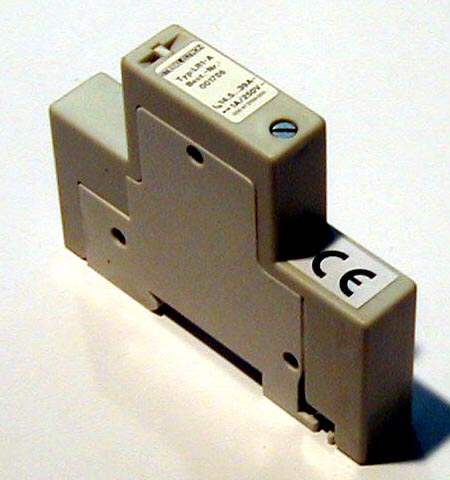
A load shedding relay is activated via the control circuit ( terminals A1 and A2; see illustration). It depends on the current flowing through it. If it exceeds a certain threshold value , called the response current, the relay responds and switches its integrated switch (in the figure between terminals 11 and 12). If the current falls below a certain threshold value, the waste current, the relay and switch return to the idle state. The response is always (slightly) larger than the waste stream . The difference between these switching thresholds results in a switching hysteresis . It ensures reliable switching processes , in particular that the relay does not carry out unwanted, too fast or too frequent switching processes in the event of slow current changes or small current fluctuations around the threshold value. A load shedding relay therefore has the functionality of a current-sensitive threshold switch .


The load shedding relay is switched (via terminals A1 and A2) in series with the priority (or the one to be monitored) consumer. There are also versions based on the push- through current transformer principle , in which the connection wire of the priority consumer is only fed through an opening.
The switching status is further processed via the switching contacts (in the figure, terminals 11 and 12) of the load shedding relay. If higher currents are to be switched in this circuit , an additional relay or contactor is usually required, as the contact load capacity of the load shedding relay is usually not sufficient for this.
Application examples
Priority switching
Load shedding relays are used when several high-performance electrical devices are connected behind a main connection, for example a night storage heater and a water heater , which, if used at the same time, would overload the main connection. In such a case, a load shedding relay is installed in the supply line to the water heater, which interrupts the supply voltage to the night storage heater via a contactor while hot water is being drawn off . The priority circuit thus implements the either-or operation ( XOR link ) of two consumers, with the priority consumer being prioritized.
The jointly used supply cable can thus be used twice (for instantaneous water heater and night storage heater) without the cross-sectional areas of its cores having to be correspondingly larger for the simultaneous operation of both consumers. It is sufficient if the cable is dimensioned for the stronger of the two consumers. This can result in cost savings in the construction.
Saving electricity costs
Load shedding relays are also used in commercial and industrial environments if, according to the electricity tariff, not only the total drawn but also the highest maximum drawn must be paid for. For example, a hotel that operates several sauna cabins can prevent all ovens from heating up at the same time.
Operational status acquisition
Since a load shedding relay trips when a certain tripping current is exceeded, it can be used, for example, to signal the "On / Off" operating states of a consumer or to record them for further processing.
So z. B. a simple automatic switch-on for an extraction system can be implemented. As long as at least one of several circular saws is running, the extraction system should also be active. Each of the circular saw electric motors is connected in series with a load shedding relay, and all NO contacts of the load shedding relays are connected in parallel ( OR link ) and in turn in series with the extraction system.
Executions
- Most load shedding relays have a fixed tripping current. However, there are also versions in which the tripping current can be adjusted. These are so-called "electronic load shedding relays", which measure the flowing current mostly without resistance via an inductive current transformer - compare it with the shedding current (maximum current) that can be set on a potentiometer - and control a relay or semiconductor relay through electronics ( comparator with hysteresis ) . One such type is the ELAR-20.
- Relays with coils are usually installed as the triggering components . Classic, electromechanical , potential-free switches that are mechanically coupled to the relay coils are usually used as switches . However, versions with electronic switches are also available.
- Load shedding relays with an NC contact as a switch are common. Less common, but also available, are versions with a normally open contact or a changeover contact .
- Special versions allow several subordinate consumers to be switched off and on again in stages - depending on the current consumption of the priority consumer.
- Most load shedding relays are as modular devices for rail mounting designed, but may also include other housing mounting positions have. As a series installation device, they usually have a space requirement of 1 module .
- While load-shedding relays are usually instantaneous, some manufacturers also offer special versions with drop-out or trip delay.
See also
Web links
- Picture of a load shedding relay for DIN rail mounting (JPG; 32 kB)
Individual evidence
- ↑ a b Alexander Rosenkranz: A load shedding relay protects the power grid. In: heizung.de. Viessmann Group, June 30, 2018, accessed on December 31, 2018 .
- ↑ a b c d e Product information load shedding relay E451. ABB , accessed December 25, 2018 .
- ↑ a b c d e f g Installation switchgear catalog. (PDF; 9.4 MB) Eaton , June 13, 2017, pp. 207–208 , accessed December 26, 2018 .
- ↑ a b Connection diagram for priority switching using a load shedding relay (example for instantaneous water heater and heat storage heater). (JPG; 329 kB) Doepke Schaltgeräte, accessed on December 30, 2018 .
- ↑ Data sheet for a load shedding relay with a through-hole current transformer , accessed March 9, 2019
- ↑ Electronically controlled instantaneous water heater - operation and installation. (PDF; 4 MB) Stiebel Eltron , April 26, 2017, p. 14 , accessed on December 30, 2018 .
- ↑ Load shedding relay. Doepke Schaltgeräte, accessed December 30, 2018 .
- ↑ Load shedding relay. Hager , accessed December 30, 2018 .
- ↑ a b c d Load shedding relay range. Eberle, accessed December 25, 2018 .
- ↑ ELAR-20 electronic load shedding relay
- ↑ a b Load shedding relay ELAR-20 normally open. Eberle, accessed December 26, 2018 .
- ↑ a b Product information load shedding switch LSS1 / 2. ABB , accessed December 25, 2018 .
- ↑ Load shedding relay RLR 1. Doepke Schaltgeräte, accessed on December 30, 2018 .
- ↑ Load shedding relay RLR 2. Doepke Schaltgeräte, accessed on December 30, 2018 .
- ↑ Product information load shedding relay E452. ABB , accessed December 30, 2018 .