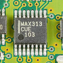
Electronic switch

An electronic switch , also an analog switch or a semiconductor switch , is part of an electronic circuit that performs the function of an electromechanical switch . Field effect transistors (FET) and bipolar transistors as well as diodes are used as switching elements . In combination with series resistors, bipolar transistors are also referred to as digital transistors in switching applications . In a broader sense, thyristors and semiconductor relays are also counted among the electronic switches.
General
Electronic switches work much faster than mechanical relays or mechanical switching contacts and work without bouncing or wear. Compared to them, however, they have a higher contact resistance when switched on and a lower insulation capacity when switched off.
When switched on, electronic switches have an electrical connection from the input to the output; when switched off, the input is electrically isolated from the output as well as possible. Since electronic switches have significantly shorter switching times in the range of less than a nanosecond , they are primarily used as fast switches in the field of analog signal processing . Examples are the switching element in sample-and-hold circuits in analog-digital converters or for switching signals in switching matrices.
The electrical properties of an electronic switch are characterized by the following values:
- Forward resistance (usually ≤ 100 Ω)
- Blocking resistance (usually ≥ 1 MΩ)
- Voltage range in which the input voltage is transmitted without distortion.
- Switching time (usually less than 1 µs)
- Type of digital control - in many cases a TTL and CMOS compatible control signal.
The following values are also specified for analog switches:
- electrical capacitance of the switching path to the rest of the circuit
- The electrical charge that is exchanged during the switching process due to the activation; This should be as small as possible, because it leads to an interference voltage pulse on the signal line
Types
Field effect transistors as switches

In the case of field effect transistors, when the voltage between drain-source is low, the resistance between drain-source can be controlled linearly via the voltage between the gate-source connections. This behavior can be used in electronic switches.
In the adjacent circuit, the JFET is switched on by a control voltage U St equal to the maximum possible positive input voltage. It is switched off in that the control voltage U St is a few volts below the lowest input voltage. For control, additional level converters, not shown, are therefore necessary, which draw the necessary control voltages, for example from a charge pump .
If, instead of a JFET, metal-oxide-semiconductor field effect transistors (MOSFET) are used as switches, as shown in the second circuit on the simplified circuit of a CD4066, there is no need to generate the necessary control voltages. Two MOSFETs, one n-channel and one p-channel, must be provided in parallel for this. They represent a so-called transmission gate . This electronic switch is switched on by a positive voltage U St = U b and switched off by U St = 0 V. Depending on the level of the input voltage in relation to the control voltage, either the n-channel MOSFET conducts when switched on, this is the case with low input voltages of up to U b / 2, and above that the p-channel MOSFET.
Diodes as switches
Because of their high blocking resistance and comparatively low forward resistance, diodes are also suitable as electronic switches. They are biased for switching operation and, with suitable diodes, allow very fast switches with switching frequencies above 1 GHz. For this purpose, the actual switching diodes are arranged in a so-called bridge circuit, as denoted by 4D in the adjacent circuit . When switched on, the four diodes are biased by the two constant current sources I when the control voltage U s is positive. In this case the output voltage U a is equal to the input voltage U e .
In the switched-off state, this is the case with a negative control voltage U s , the current I of the two constant current sources is diverted via the two additional diodes D ', whereby the four diodes in the bridge block. The output is thus isolated from the input with high resistance.
The diodes must have a small junction capacitance and a low differential resistance in the conductive case. The second requirement requires a relatively high current in the forward direction, since the differential resistance of a diode is inversely proportional to the current. A lower differential resistance can also be achieved for high frequencies if the service life of the charge carriers in the diode is long enough, as is the case with the pin diode . For this reason, pin diodes are also used as DC -controlled HF switches .
literature
- Ulrich Tietze, Christoph Schenk: Semiconductor circuit technology . 12th edition. Springer, 2002, ISBN 3-540-42849-6 . Berlin

