
PRR class DD1
| Pennsylvania Railroad DD1 | |
|---|---|
 PRR DD1 3998
|
|
| Numbering: |
Double locomotives: PRR: EZN10 – EZN42 LIRR : 338–360 Locomotive halves: 3932–3949 3952–3999 |
| Number: | Double locomotives: 33 locomotive halves: 66 |
| Manufacturer: | PRR Altoona Westinghouse |
| Year of construction (s): | 1909-1911 |
| Axis formula : | 2'B + B2 ' |
| Gauge : | 1435 mm ( standard gauge ) |
| Length over coupling: | 19,790 mm |
| Service mass: | 142 t |
| Wheel set mass : | 22.58 t |
| Top speed: | 137 km / h (85 mph) |
| Hourly output : | 1567 kW |
| Continuous output : | 1180 kW |
| Starting tractive effort: | 294 kN |
| Hourly traction: | 74 kN at 61 km / h |
| Continuous tensile force: | 40 kN at 93 km / h |
| Driving wheel diameter: | 1830 mm |
| Power system : | 650 V DC |
| Power transmission: | Busbar |
| Number of traction motors: | 2 |
The class DD1 of the Pennsylvania Railroad (PRR) were electrically powered double locomotives with the wheel arrangement 2'B + B2 ', the power of which came from a 650 V power rail coated from above . Before the locomotives were built, driving dynamics tests were carried out to determine the most suitable design.
history
At the beginning of the 20th century, the PRR under the direction of Alexander Cassatt fired at the construction of the Pennsylvania Station in Manhattan . This underground passenger station was connected to the railroad network with tunnels under the Hudson River and the East River , creating a continuous rail link from Washington, DC - New York City - Boston , the Northeast Corridor . Cassatt was impressed with the cleanliness of the recently opened Gare d'Orsay in Paris , where electric trains operated with power from the third track , so this system should also be used in New York.
In 1905 two test locomotives were built:
| Numbers | class | Manufacturer | Axis formula | drive | image |
|---|---|---|---|---|---|
| 10001 | AA1 | PRR Altoona | Bo'Bo ' (Bo' – Bo') |
Pawbearing drive |

|
| 10002 | AA1 | PRR Altoona | Bo'Bo ' (Bo' – Bo') |
Pawl bearing drive , |

|
Locomotive 10002 had a bogie with a pawl bearing drive and one with axle motors . During test drives on the Long Island Rail Road (LIRR), both locomotives showed poor running characteristics at higher speeds: they lurched in the track and made strong lateral movements. A third test locomotive was therefore built in 1907:
| Numbers | class | Manufacturer | Axis formula | drive | image |
|---|---|---|---|---|---|
| 10003 | Odd D | Baldwin | 2 B | Axis motors with hollow shaft drive |

|
To investigate the driving dynamics of the various locomotives, a test set-up was set up in 1907 near Franklinville NJ on the West Jersey and Seashore Railroad (WJ&S). WJ&S was a subsidiary of the PRR. For this purpose, 80 sleepers were prepared in order to record the forces acting on the rails. This was done by means of a hardened steel ball in each sleeper, which was pressed against a metal plate by the transverse bending of the rail. The depth of the spherical impression was a measure of the transverse bending of the rail.
Two PRR steam locomotives and a New Haven electric locomotive were also examined with the locomotives listed above . The EP-1 class electric locomotive had the Bo'Bo 'wheel arrangement, and unlike the 10001 and 10002 locomotives, the bogies were not closely coupled to one another . So that the AC vehicles could run on the WJ&S, they were given a converter car . The measurements were carried out both on a straight stretch of track and in an arc of 1750 m radius. The measuring section was 50 m long.
| class | Manufacturer | Axis formula | image |
|---|---|---|---|
| PRR D16b 6032 | PRR Altoona | 2 B |

|
| PRR E2 6020 | PRR Altoona | 2'B1 ' |
.jpg)
|
| New Haven EP-1 028 | Baldwin | Bo'Bo ' |

|
The driving dynamics tests with the six locomotives mentioned above led to the following result:
- the steam locomotives and the 10003 showed good running characteristics at all speeds and in both test sections
- the EP-1 of the New Haven tended to lurch on the straight track. The locomotives of this series were therefore later equipped with additional running axles, which resulted in the wheel arrangement (1'Bo) (Bo1 ').
- the 10001 and 10002 fared worst. They lurched heavily on both test tracks and exerted lateral forces on the rails that were twice as large as those on the steam locomotives.
The engineers therefore rejected the idea of a bogie locomotive . They assigned the good running properties of the 10003 to the asymmetrical wheel alignment and the high center of gravity. They therefore gave priority to the America 2'B wheel arrangement. In order to achieve higher tensile forces, two 2'B units were connected back to back with close couplings . The hollow shaft drive with axle motors from the Odd D was not adopted and the cheaper helical rod drive was installed instead. According to the specifications, the DD1 had to be able to carry 800 t passenger trains over the 18 ‰ ramps into the New York tunnel.
business
The total of 33 double locomotives were mainly used on the tunnel route under the Hudson River between the Manhattan Transfer stations and Pennsylvania Station in New York City. The first regular passenger train hauled by a DD1 left Penn Station on November 27, 1910.
The locomotives had an enviable reputation for efficiency and low maintenance costs. In the first four years, the locomotives covered 6.3 million km and only caused 45 breakdowns on the route, causing 271 minutes of delay. The maintenance costs were only 2.2 cents per kilometer in the first four years.
From 1924 the new class L5 locomotives were delivered, so that 23 locomotives of the DD1 series were delivered to the Long Island Rail Road (LIRR) operated by the PRR , where they were given the road numbers 338 to 360. Most of the LIRR's DD1s were shut down and scrapped between 1949 and 1951.
In 1933, overhead line operations began in the New York tunnels so that the GG1- hauled express trains could run directly to Penn Station. Some of the remaining DD1s at PRR were still used to transport empty trains between Penn Station and the Sunnyside Yard depot in Queens .
The last two DD1s were retired in the 1960s, with the locomotive with halves 3936 and 3937 given to the Railroad Museum of Pennsylvania and listed as a monument on the National Register of Historic Places .

PRR 3936 and 3937

Frame with drive motors and rod drive
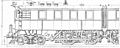
Side view, sketch

Pennsylvania Station tunnel exit


technology
The machines consisted of two closely coupled halves, each with two coupling axles mounted in the frame and a leading bogie . The overhead, slow-running 315-A drive motor from Westinghouse drove both coupling axles via a helical rod drive with a jackshaft and 90 ° crank offset . Westinghouse's electrical equipment was built on a load-bearing floor frame. The locomotive body and driver's cabs could be lifted off for maintenance.
The running bogies carried the pantographs on both sides for the busbars coated from above. The engine power allowed a speed of 85 mph or 137 km / h, the regular, the operational requirements adjusted driving speed was a maximum of 40 mph or 65 km / h.
The entrances to the driver's cabs were on the end faces equipped with open end platforms. In addition, there were open crossings to the wagon train for the staff.
literature
- Alvin F. Staufer: Pennsy Power . Steam and electric locomotives of the Pennsylvania Railroad, 1900-1957. In: Issuu . Standard Print & Pub. Co., Carrollton, Ohio, LCCN 62-020878 , pp. 248-253 ( issuu.com [accessed January 7, 2018]).
Web links
Individual evidence
- ^ William D. Middleton: When the Steam Railroads Electrified . 2nd Revised ed. Indiana University Press, Bloomington 2002, ISBN 978-0-253-33979-9 , pp. 126 .
- ↑ Alvin F. Staufer, p. 247
- ^ Brian Solomon: Electric Locomotives . Voyageur Press, ISBN 978-1-61060-626-4 , pp. 44–45 ( google.ch [accessed January 7, 2018]).
- ↑ a b c Alvin F. Staufer, p. 248
- ↑ Alvin F. Staufer, p. 246