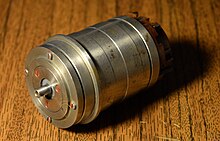
Resolver
A resolver is an electromagnetic measuring transducer for converting the angular position of a rotor into an electrical variable. Other angular position encoders or angle encoders are, for example, potentiometer encoders , incremental encoders and absolute value encoders .
principle
Two stator windings offset by 90 ° are arranged in a cylindrical housing , which surround a rotor with the rotor winding that is mounted in the housing . The rotor winding is led to the outside via slip rings and brushes . Today's resolvers are usually brushless, the information from the rotor is transmitted inductively. In contrast to an incremental encoder , the resolver delivers an absolute angle signal within one revolution (pole pitch) and therefore does not have to be referenced after switching on.
Stator excitation
The stator winding S1 is excited with a sinusoidal alternating voltage ; the stator winding S2 is excited with an alternating voltage which is shifted by 90 ° compared to S1. The phase position of the voltage induced in the rotor winding depends on the position of the rotor:
- if the rotor is exactly opposite the stator winding S1, the phase position of the rotor voltage is 0 °,
- if the rotor is opposite the stator winding S2, the phase position of the rotor voltage is 90 °,
- If the rotor is in the middle between S1 and S2, the phase position of the rotor voltage is 45 °.
During one rotation of the rotor, the angular position encoder supplies an alternating voltage, the phase position of which rotates from 0 ° to 360 °. The phase position of the output voltage of the rotor in relation to the excitation voltage at S1 is therefore a measure of the angular position of the rotor.
Rotor excitation
Alternatively, the rotor winding R is excited with a sinusoidal alternating voltage. The amplitudes of the voltages induced in S1 and S2 depend on the angle of the rotor and correspond to the sine and cosine of the angular position of the rotor. The angular position is calculated from the amplitudes and through
Designs
In addition to the 2-pole angular position encoder described, there are also multi-pole designs. A 4-pole angular position encoder delivers a phase shift of 2 × 360 ° with one rotor revolution. Differential angle position encoders have two rotor windings offset by 90 °, i.e. they supply two output voltages offset by 90 °.
With brushless angular position sensors, the rotor voltage is transmitted to the outside by means of a rotating transformer.
An inductive rotary encoder with three stator coils offset by 120 ° is called a synchro .
application
The output signal of the angular position encoder can be used directly for display with a suitable device or it can be amplified or digitized and fed to a measuring or control device. Wherever the angular position of a mechanical element is of interest, angular position encoders have been used, for example rudder position on ships , position of control elements in chemical plants and in power plants or as position encoders in controlled machine tools and industrial robots . Older radars and rotating radio and broadcast antennas as well as electric waves also used resolvers.
Resolvers have often been replaced by optoelectronic , digital angular position encoders as well as other incremental encoders and absolute encoders, but still hold their own as a robust and cost-effective solution in many applications such as textile machines, mining machines and servomotors. One advantage of the brushless resolver is that apart from the bearing, they work without wear, while soiling is always to be expected with optoelectronics. In systems that are supposed to run for a long time, there is also a limited service life of the LEDs .
The robust construction allows resolvers to be used in liquid nitrogen (−197 ° C), in high vacuum (up to +200 ° C) and in highly radioactive environments, i.e. areas in which other position sensors fail.
literature
- Jerome Kessler (Ed.): Synchro / Resolver Conversion Handbook . 5th edition. Data Device Corporation, company publication , 1999, LCCN 74-077038 ( ddc-web.com [PDF; 1.5 MB ] First edition: 1974).


