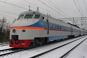
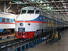
SŽD series ЭР200
| SŽD series ЭР200 (ER200) | |
|---|---|
|
SŽD series ER200
|
|
| Number: | 3 train sets |
| Manufacturer: | Rīgas Vagonbūves Rūpnīca |
| Year of construction (s): | 1973 and 1994 |
| Gauge : | 1,520 mm |
| Length over coupling: | 208,000 mm (8 parts) |
| Height: | 4,200 mm |
| Width: | 3,130 mm |
| Trunnion Distance: | 18,800 mm |
| Bogie axle base: | 2,500 mm |
| Empty mass: | 442.4 t |
| Service mass: | 60 t (drive car) |
| Wheel set mass : | 17 t |
| Top speed: | 200 km / h |
| Continuous output : | 1,720 kW |
| Acceleration: | 0.4 m / s² (0-60 km / h) |
| Braking delay: | 0.4 m / s² (80–0 km / h) |
| Driving wheel diameter: | 950 mm |
| Power system : | 3 kV = |
| Power transmission: | Overhead line |
| Seats: | 416 |
The ЭР200 (ER200) was in Riga Wagon Factory (RVR) in Latvia built high speed - Multiple Unit .
history
In mid-1971, plans of the Soviet State Railways became known to develop an express multiple unit for the Moscow – Leningrad route . With a top speed of 200 km / h, the travel time between the two cities should be shortened from just under five to four hours, corresponding to a travel speed of 162 km / h. Depending on the traffic requirements, the ER-200 trains should have eight to 14 cars. The train consisted of powered intermediate cars, some of which were equipped with pantographs , and non-powered control cars .
A first multiple unit was built in 1973. It was given the designation ER200, where E stands for electric, R for the place of manufacture in Riga , 200 for maximum speed. A maximum speed of 236 km / h was achieved on test drives. From 1984 the train was used as scheduled on the Moscow – Leningrad line. Two additional control cars (as a reserve) were built in 1988. Then it was decided to build another ER200 train. The second ER200 - (2) train was completed during the 1991-1994 crisis. Until 1993, the two reserve control cars were used to form a third ER200 train, which ran as a 6-car train from Saint Petersburg to Novgorod on weekend days.
The ER200 had during its start is very important for the image of the Soviet state railways, similar to today, the Intercity Express for the German railway . For example, images of the ER200 could be seen on numerous articles in the dining car of conventional trains .
There were concrete plans to replace the ER200 with a newer train ЭС250 (ES250, called Sokol ("falcon"), Russian Сокол ). However, the project was abandoned for various reasons, mainly quality.
In 2008, a control car and three intermediate cars of the first ER200 were handed over to the St. Petersburg Railway Museum. On February 20, 2009, the last scheduled journey of the ER200 between Moscow and Saint Petersburg was undertaken. In May 2009 two ER200 wagons (a control car and an intermediate car) were handed over to the Moscow Railway Museum. In 2011 a control car and two intermediate cars were transferred to the Samara Railway Museum .
The successor to the ER200 is a Velaro manufactured by Siemens in Germany , called Sapsan ("Peregrine Falcon", Russian сапсан ), which went into operation on December 18, 2009 and is a further development of the German ICE 3 . This went into operation at initially up to 250 km / h; a possible increase in the maximum speed to 300 km / h for use on the planned new high-speed line between Moscow and Saint Petersburg is planned.
Constructive structure
Car body
The car body is a self-supporting structure as a tube. An aluminum-manganese alloy was used as the material for the car body, with which a box profile consisting of longitudinal and transverse profiles was constructed and clad with sheet metal. The entire car body was assembled from the frame, the two side and end walls, the roof and the floor.
The end cars consisted of the driver's cab, an open-plan compartment with 28 seats, a conductor's compartment and a bar room. The intermediate car had an open-plan compartment with 68 seats. These were designed to be rotatable and had an adjustable backrest. With a uniform length of 26 m, all cars had access doors at the ends with corresponding entry areas. The seats were separated from each other by central aisles with a width of 600 mm.
Due to the high speed of the multiple unit, the windows of the cars did not open and the passenger compartments were ventilated by means of an air conditioning system. This was equipped in such a way that with an outside temperature in the range of ± 40 ° C, an inside temperature of 22 ° C could be achieved. The air conditioning system was located under each car and had a cooling capacity of approx. 29 kW, which allowed an hourly air circulation of 5,000 m 3 per car. All vehicles in the train were given extensive thermal and sound insulation. All of the cars have a continuous telephone and telephone system.
Propulsion system
Every two carriages of a train formed an electrical unit. While the main driving equipment was installed below the floor in one drive car, in addition to the pantographs, the auxiliary equipment was in the other car. The main driving equipment included the control for all traction motors in thyristor design as well as the starting and braking resistors. The auxiliary equipment included the motor generator, the battery accumulator with charging device and the compressors for the compressed air system . The automatic circuits, the magnetic rail brake and the emergency lighting were fed from the battery accumulator with charging device. The generator fed the asynchronous motors of the air conditioning system, the fans for cooling the starting and braking resistors and the vehicle lighting. The train's control cars also had this auxiliary equipment. In addition, a frequency converter to 400 Hz and automatic units for automated train guidance were installed here.
Each drive motor had an output of 215 kW. With an axle arrangement of Bo 'Bo' the middle car possessed z. B. the twelve-part train in the range from 0 to 120 km / h an acceleration of 0.32 m / s 2 . The remaining acceleration up to 200 km / h was achieved with 0.05 m / s 2 . This made it possible to reach the top speed of 200 km / h after 4.5 minutes and 9 km of travel and to be able to maintain it even on an incline of 8 ‰.
drive
The bogie frame consisted of two cranked longitudinal girders as well as two frontal and one central crossbeam, which also took over the guidance through the pivot pin. The traction motors were elastically mounted in the bogie frame. An elastic coupling led from the drive motor to the single-stage gearbox, which on the one hand was elastically attached to a console of the frame cross member and on the other hand was supported on the axle shaft. The gear ratio was 1: 2.35. With the exception of the first two wheels of the control car, all wheels had an electropneumatic disc brake, which worked together with the electric brake .
Particular attention was paid to the running and spring properties of the car. The bogies received a two-stage spring suspension, namely coil springs with hydraulic dampers for the primary suspension and air springs for the secondary suspension. This suspension was particularly suitable for damping high and low frequency vibrations in the horizontal as well as the vertical and consisted of a fabric covering made of rubber and cord fabric. The position of the car body was constantly set and monitored automatically, which was done with the help of regulators located at the ends of the lower spring support beam.
Braking device
The train was equipped with three different brake systems, namely with the electro-pneumatic disc brake , the magnetic rail brake and the electric brake in the drive car. With the latter, the energy gained could not yet be fed back into the contact line, but was destroyed in load resistors. The braking deceleration of the electric brake from 200 km / h to 80 km / h was approx. 0.45 m / s 2 . With the activation of the electropneumatic disc brake , this deceleration could be increased to 0.8 m / s 2 . Both brake systems could be coupled via an electropneumatic controller.
In the case of an emergency or emergency braking, the magnetic rail brake was also used , so the braking distance from 200 km / h to a standstill was approx. 1,600 m.
Auxiliary equipment
Since the ЭР200 was not intended to be operated on special track systems, special control and monitoring devices were necessary for its operation on the intended route.
For example, the vehicle included an automatic speedometer. It received the information about the covered speed from the axis encoders and displayed deviations between the specified and permissible speed.
Upon delivery, the multiple unit had an automatic train control system, which meant that the train driver had to concentrate fully on observing the route. The system worked with an accuracy of ± 30 s and kept the train driver informed about the proper functioning of the system. This program had data for the distance, time and permissible speed on the route, it maintained the permissible speed in a range of ± 5 km / h, switched on or off traction motors if necessary and controlled the braking system.
The vehicle also had an electronically controlled anti- skid and anti-skid device . As soon as a drive axle tended to skid, the tractive force was regulated accordingly via thyristors and the slip was eliminated. In addition, this system prevented an excessive braking effect.
See also
literature
- The model railroader 11/1973, vehicle archive, page 337, organ of the DMV
Web links
- Detailed description on emupages.narod.ru with information table ( Memento from July 1, 2002 in the Internet Archive ) (Russian)
- Description on drezina.ru (Russian)
- A rare picture: all three ER200s in their trunk depot
- Film recording with the ER 200 passing at moderate speed
- Photograph of the entire ER 200 on railpictures.net
- Description of the ER 200 project to be replaced on rail4.net
Individual evidence
- ↑ Report Soviet multiple units for a top speed of 200 km / h . In: Die Bundesbahn, year 45 (1971), issue 12, ISSN 0007-5876 , p. 622.
- ↑ Karl Johaentges , Jackie Blackwood: Lisbon - Hong Kong by train, Stürtz, Würzburg 1996, ISBN 3-8003-0795-2 , S. 90th
- ↑ Message Faster to St. Petersburg . In: Eisenbahn-Revue International , issue 1/2001, ISSN 1421-2811 , p. 17.
- ↑ Der Modelleisenbahner 11/1973, vehicle archive, page 338, organ of the DMV
- ↑ Der Modelleisenbahner 11/1973, vehicle archive, page 338, organ of the DMV
- ↑ Der Modelleisenbahner 11/1973, vehicle archive, page 338, organ of the DMV
- ↑ Der Modelleisenbahner 11/1973, vehicle archive, page 338, organ of the DMV


