Speedometer

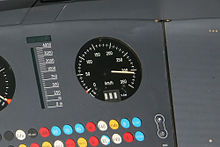
A speedometer (from ancient Greek ταχύς tachýs "fast" and μέτρον métron " measure , scale") is a device for measuring and displaying the amount of the speed of a land vehicle. Usually there is an analog display on a scale by the “speedometer needle” (pointer tachometer). In rare cases, a bar display (roller tachometer) , also analog, or a digital display using a numeric display (digital tachometer ) or a bar display on an LC display is used. If the values are recorded, one speaks of a tachograph or tachograph. If the speed signal comes from a computer to which several speed sensors may be connected, the visible part is technically called an indicator . The legislature calls the whole thing a "speedometer", the part that contains the display as a "speedometer". Usually the odometer ( odometer ) is also connected to the speedometer , as they have a common drive.
History and operating principles
Most speedometer are of the measuring principle ago actually tachometer . The first purely mechanical tachometers were based on centrifugal force . The German mechanical engineer Diedrich Uhlhorn is considered to be the inventor and first used this in 1817 for textile machines. From 1844 this measuring principle was used on locomotives - the Daniel tachometer for locomotives did not have a circular display, but a cardboard disk with a pin - a centrifugal pendulum lifted the pin and a clockwork turned the disk.
When 1888 of the Croat Josip Belušić patented under the name "Velocimeter" eddy-current tachometer rotates a permanent magnet and formed in a front-mounted metal disc or bell aluminum eddy currents . The additional field energy of the eddy currents would be avoided if the rotatably mounted disk were to rotate with it. But it is prevented from doing so by a return spring. The magnetic field increases linearly with the speed, the field energy increases with the square, the force effect as its derivative again linearly, as does the restoring force of the spring with its angular deflection. This means that the deflection of the disk with a pointer is proportional to the speed. The pointer is backed with a calibrated scale. The magnet material used has a high Curie temperature in order to keep the temperature drift of the measurement error small.
In 1902 the German inventor Otto Schulze developed the eddy current tachometer, a construction for road vehicles. Schulze relied on a flexible shaft ( speedometer shaft ), with which the speed of the wheel or gearbox is transmitted to the speedometer and there set a magnet in a rotational movement. This speedometer cable was prone to wear and tear and caused an unsteady display if there was too much friction due to jerking. For long transmission paths, for example in rail vehicles, a resolver was used instead of the speedometer cable . The response receiver at the end of the electrical connection was located in the display and drove an eddy current tachometer there. It was easier to rectify the alternating voltage of a tachometer generator and to display the direct voltage - which is wavy at low speed - with a moving coil instrument.
Incremental encoders generate a frequency proportional to the speed, which can be converted into a voltage with an analog circuit. The first production vehicle with such a system was the Porsche 911 Turbo . The encoder in the differential consisted of a magnetic pole wheel and a reed contact . Modern cars have sensors on each wheel (for ABS, ASR, ESP, navigation), the frequency of which is recorded by a microcontroller . The primary measurement result is the number of pulses within a specific measurement interval or, better still, the period between signal edges.
The advertisements have also changed. Pointers are moved completely linearly and independently of temperature by a stepper motor over a much larger angle or are simulated on a display, often in connection with various other displays, see instrument cluster and multifunction display . With other variants it is particularly important that certain important speed ranges are shown spread out so that the driver can read them more precisely. Nowadays, the speed is often displayed as a numerical value, especially in head-up displays .
Measurement errors and tolerances
All the methods presented here are not based on the direct measurement of the distance covered in a certain time , but on a speed measurement and are therefore dependent on the rolling circumference of the wheels. If larger or smaller wheels are mounted, a speedometer adjustment is necessary. Smaller error contributions that are not proportional to the speed driven are caused by centrifugal forces and slip due to increasing air resistance.
In cars, wear leads to measurement errors of a few percent, in rail vehicles they are up to over 10% and must be corrected. Under ETCS , the permissible limit for the measurement error below 30 km / h is a constant 2 km / h and increases linearly above it, up to 12 km / h at 500 km / h. For motor vehicles in Europe and many other countries, the displayed speed is not below the actual driven speed, but upwards by max. 10% v + 4 km / h (so-called speed advance).
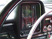
Speedometers often graphically show the speed linearly or with equidistant graduation marks, but there is no legal requirement for this. In some vehicles z. B. the range 50-60 km / h expanded or the range of higher speeds shown with decreasing graduation intervals. In order to achieve a display proportional to kinetic energy or the required braking distance and risk, the speed can be displayed on a quasi-logarithmic scale (see illustration), as was done in a similar way with the GS and CX models from Citroën in the 1970s. However, this leads to a correspondingly difficult to read speed in the lower speed range.
Speed indicator

Speed indicators on the roadside serve as feedback for drivers of motor vehicles and warn them to adhere to speed limits.
In the study Evaluation of Dynamic Speed Feedback published in 2010, the Accident Research of Insurers (UDV) carried out a comparison of these dynamic speed displays with the so-called dialog display. Although the dialogue display does not show the current speed and only praises and rebukes it by showing "Thank you" and "Slow", there were stronger and permanent decreases in average speeds.
See also
- Airspeed indicator on the aircraft
- Continuous wave radar for speed over ground in rail vehicles as well as for testing the driving behavior of automobiles
- Inertial navigation
- Speed measurement at the ship ( log )
- Bike computer
literature
- Motor vehicle measuring devices: Devices for measuring speed In: KFT 2/1957, pp. 54–57.
Web links
swell
- ↑ a b ECE regulation R 39 ( Memento from May 15, 2012 in the Internet Archive ) (PDF; 867 kB)
- ^ [1] Meyers Konversations-Lexikon, 4th edition (1885–1890)
- ↑ spiegel.de: 100 years of speedometer, speedometer only slowly got up to speed
- ^ Jörg Austen, Sigmund Walter: Porsche 911 - The technical documentation. Motorbuch Verlag, Stuttgart, 1995, ISBN 3-613-01689-3 , p. 71.
- ↑ C. Schulze, T. Gehlert: Research report VV 03: Evaluation of dynamic speed feedback. 2010, ISBN 978-3-939163-27-5 .


