
hinge


Hinge is a colloquial term for a about an axis of rotatable joint ( degree of freedom f = 1), in particular, as fitting of simple flaps on furniture and containers is used. Hinges on doors, windows, and boxes are also known as straps or hinges .
In addition to single-joint hinges, in which the parts connected to them (doors, flaps, etc.) move on circular paths around the fixed axis (e.g. attached to the door frame), multi-joint hinges are also used. In principle, this is a coupling gear ( guide gear ). These have several axes ( joints ). In this way, suitable trajectories can be implemented for the respective purpose, which may deviate from circular paths.
Single-joint hinges can be made separable or inseparable (see picture) . Originally, the terms band (separable) and hinge (inseparable) were common. Due to the development of various new designs, this classification is no longer applicable today.

The naming of the individual parts is not handled uniformly either (tabs, trade, tabs, bolts, pins, tenons, rollers, bushings, etc.) .
Simple hinges will i. d. R. of two sheet metal strips fabricated by respectively a side bent over to one or more cylindrical rollers (rolled) is. The rollers are positioned next to each other so that a pin can be inserted through the center of the rollers. The pin serves as the axis around which the wings of the hinge rotate. Space-saving and material-saving hinges are made of thin sheet metal and have several rolls next to each other. See also piano hinge and flap hinge . Instead of rollers, eyelets that rotate around the pin axis are also used.
term
The word "hinge" was borrowed from French in the 18th century . The French charnière “hinge (joint)” goes back to the Latin cardo “door hinge, turning point”, from which the word cardinal “fundamental” is derived.
Hinge or tape
The terms tape and hinge are often used synonymously . The preference for one of the terms in certain contexts has historical reasons.
Belts are traditionally made of steel strip produced and at a pin or pins of a fishing rotatably mounted. Traditionally, hinges were often made of sheet steel and had two similar parts ( strap lugs ), one of which was fixed in place while the other could move around it on the common axis. The DIN EN 1527 Building hardware - Hardware for sliding doors and folding doors - Requirements and test methods uses the term hinge specifically as fitting that connects the two folding doors with each other while doors otherwise to door hinges are hung.
Particularly long furniture hinges are made from sheet metal strips. Since they are used, among other things, to fasten the flap over the keyboard of pianos, they are often referred to as piano hinge. See rod hinges .
Wooden flaps and covers and door leaves and window shutters from boards or scantlings have traditionally been commonly assigned to stabilize iron bands ( fogged ). At the same time, these were also used for the movable suspension of the elements by bending the straps into a roll at the end. Hinges on doors, windows and flaps are therefore still called bands today. The pin that is attached to the door frame to carry the tape is also known as a hinge or block .
Executions
Profile hinges
Profile hinges are robust hinges with a high load capacity. They are widely used in vehicle construction , switch cabinet construction and similar areas.
Door hinges
Door hinges usually consist of an axis and at least two bushings or rollers . To fasten the hinges to the door leaf with screws or nails , they are connected with perforated sheets or strips. The sockets are also welded to steel doors . The side of the door that the door hinge is on is called the hinge side or hinge side .
Modern door hinges are z. B. Drill-in hinges and cross hinges (see below).

Drilling hinge (principle)
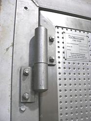
Heavy hinge on a steel door leaf
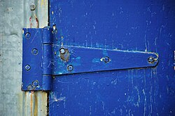
Simple door hinge for fastening the lid of a box
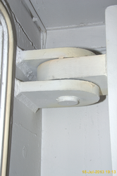
Welding tape of a heavy hatch door on a ship


Flap and furniture hinges
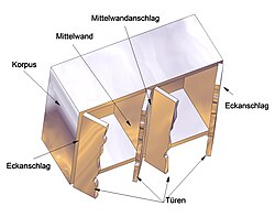
A furniture hinge is a swivel joint that attaches a furniture door to the body .
The stop indicates where a door is attached to the body with hinges:
- With the overlying or corner stop , the axis of rotation of the door fastening is on the outer edge of the side panel of the body.
- With the inset or inside stop , the door leaf lies within the body so that the edges of the side panels as well as the top cover plate and the lower base plate remain visible.
- In the case of a rebated stop , a rebate is cut in the door leaf or body so that the door leaf lies both inside and outside the body.
- In the case of the central wall or twin hinge , two doors opening in opposite directions are hinged on a central wall dividing the body.
A distinction must be made between the left and the right stop (depending on the opening direction of the door when looking at the door leaf, see opening direction of doors ).
There are different types of stop ("on top " etc .; see picture). The hinge shapes required for this are identified by their " offset " (letters A, B, C, D and L). Simple ("straight") hinges or straps are those of offset A.
In addition to the concealed hinges and multi-joint hinges described below, there are various special hinges: angled hinge, wide-angle hinge, aluminum frame hinge, zero protrusion hinge, stud hinge (base plate increased by 3 mm), glass door hinge (26 mm cup hole), crystal hinge (to be glued), etc. .
Door stop
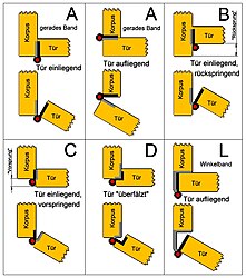
Stop types and hinge types (offset)


Simple hinges (rolled hinges)
A rolled furniture hinge consists of two parts, the trades , which are (mostly) permanently connected with a pin. This pin is often riveted. Steel, stainless steel or brass are used as material for the trade. They have the offset A (straight) .

Simple or rolled hinge
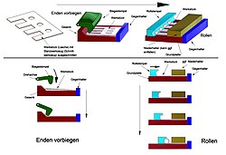
Principle of the hinge rolling (production is largely automatic)


.jpg)
Bar hinges
Unlike most other hinges, a bar hinge is long in the direction of its axis of rotation and narrow in the other direction. A piano hinge consists of two thin sheet metal strips that are alternately rolled around the central axis of rotation along one long side and thus form a row of swivel joints . In addition to the eponymous use as long hinge on keyboard covers of pianos and wings it was often used in furniture doors. A width of 16–180 mm and a material thickness of 0.7–3 mm are customary. It can be cut to any length, a common length is 3500 mm.
Today, rod hinges are also made from two extruded aluminum profiles by sliding the long, rod-shaped bead of one profile into the correspondingly shaped, concave recess of the other profile. This cavity encloses the bead only over a little more than half of its circumference, so that it is held on the one hand and on the other hand can perform a rotary movement of up to 120 degrees. The result is a continuous, linear swivel joint. In another design, two aluminum profiles are pushed on both sides over an elastomer band and connected to it (e.g. clamped) so that the elastic plastic band acts as a movable connection between the two rails of the rod hinge, as with the film hinge. This design is advantageous if the hinge also serves as a seal or a slight spring-back of the hinge is desired, as is the case with the hinges of folding doors .
Concealed hinges, concealed hinges
If a hinge is not to be visible when the door is closed, its axis of rotation ( joint ) must be countersunk in the door leaf (see 1 in the picture) . In order to be able to accommodate the hinge within the door leaf, concealed hinges were developed. These have a cylindrical cup , the "pot" , at one or both fastening points , which is inserted into a corresponding recess in the door leaf that has been sunk beforehand with a milling head or a Forstner bit. This type of fastening results in a solid connection of the hinge in the widespread, little tensile strength chipboard doors as well as simple assembly. Pot hinges are therefore also used when the hidden position of the joint is not important.
Concealed single-joint concealed hinges have the disadvantage that relatively large gaps between the door and the body (or the neighboring piece of furniture) have to be accepted in order to allow the edges of the door leaf to move freely in a circle (see Figure 1a and 1b in the picture). Smaller gaps can be achieved through doors that are less thick (compared to the body) or with rounded edges (see 2 and 3 in the picture). Multi-joint concealed hinges provide a better solution .
If concealed hinges are only mentioned, multi-joint concealed hinges are meant. Other types of concealed hinge are indicated by additional information (e.g. single-joint concealed hinge) .
A concealed hinge is also known as a concealed hinge . The base plate is attached to the body of the piece of furniture , with which the so-called lever is connected by screwing or a quick fastening (e.g. clip mechanism). In the door, the pot is fastened in a flat pot hole with a large diameter. These two parts are connected by the band arm . In the hinge arm there is usually a spring for closing the furniture door.
The cup bore usually has a diameter of 35 mm. 40 mm, 32 mm and 26 mm also occur. On the base plate, next to the pot, there are often two holes with a diameter of 3 to 8 mm for screwing on the plate. The distance between the lever and the base plate can usually be adjusted using adjusting screws, which are used to align the furniture door. If the levers are attached to the base plate with snap locks , the door leaves can be quickly attached and detached. Only a few hinges and straps can be adjusted in all three axes like concealed hinges.
The offset is also specified for concealed hinges. However, this is not defined by capital letters, but by a millimeter. The crank is understood here to mean that the strap fastening on the lever has a greater distance from the base plate than in the case of a concealed hinge suitable for a corner stop, the crank of which is set at 0 mm. Typical values are crankings of 10 mm and 16.5 mm. This is shown schematically in the picture. Cranked concealed hinges can be used for overlying center stops and inset corner stops. The joint width and the support are set using a spacer (called the distance, can be omitted if necessary) in conjunction with the adjusting screw on the lever.
Cup hinges differ in the maximum possible opening angle, the distance between the base plate and the cup and the type of fastening. Variants are the so-called push hinges, which allow the door to open automatically thanks to a special spring, as well as Silentia hinges, which prevent the door from hitting the frame when it is closed.

Concealed hinge principle
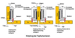
Offset on concealed hinges


Film hinges
In the case of plastic containers, hinges are occasionally used which are formed in one piece with the two elements to be connected. Such hinges essentially consist of a thin-walled connection, often in the form of a fold, which, due to its flexibility, enables the connected parts to rotate. Film hinges are usually associated with jumps in wall thickness, but should also have smooth transitions for the melt flow and stress distribution. A popular material is polypropylene because of its high wear resistance. Film hinges only have a limited load capacity; In particular, shear and increased stress on the hinge ends lead to breakage or crack. Due to their principle, film hinges are extremely inexpensive to manufacture, but if they are defective, they cannot be replaced if they were manufactured in conjunction with the base body.
Film hinges are widely used in storage containers in the kitchen and household. For example, the film hinge on the lid of the Tic Tac packaging is known.
Technically speaking , film hinges can be assigned to solid body joints or spring joints .

Tic Tac packaging

Film hinge on a PET box


Multi-joint hinges

Multi-joint hinge for a built-in refrigerator

Multi-joint hinge

Generation of closing and locking force with a compression spring

Commercially available multi-joint hinge for a built-in refrigerator


Hinges with special requirements on the path of movement of the fastened parts are usually designed as multi-joint hinges (in the form of a coupling gear or, more precisely, guide gear ). Several axes ( joints ) are connected to one another with so-called gear members. On the so-called frame (e.g. furniture body or door frame) there are (usually) two fixed axes, while the other axes of the hinge change their position when opened.
More joint hinges allow furniture doors having in rest position a distance of only a few millimeters to the adjacent door and rest against the body and at the same time when opening back to the outside without colliding with the neighboring furniture door.
As an example, a multi-joint hinge for the door of a built-in refrigerator is shown in the pictures above. The hinge is not visible on the furniture front and is hidden behind the door panel.
The hinge consists of the gear members A to F. The gear member A is attached with its two axes to the refrigerator body (frame), while the refrigerator door (and the panel attached to it) is connected to the gear member F. The edges of the door and panel move on different circular paths (shown in the animation) around the imaginary (i.e. not real) axes A1 and A2. In principle, the hinge could also have been designed so that the edges move on paths deviating from the circular path.
Multi-joint hinges are often designed in such a way that they apply locking or locking forces (corresponding torques ). For this purpose they contain compression, leaf or leg springs. Often also attenuations are installed, which z. B. is useful with upward opening hatches.
In the refrigerator hinge shown in the pictures, the gear member E (designed as a U-profile) is provided with a spring bearing rotatable about an axis, which guides a displaceable spring sleeve in a manner not shown, in which a prestressed compression spring is arranged. In a certain position of the gear mechanism, the locking pins of the spring sleeve engage in oblique slots in the gear element E, which prevents the spring from relaxing (locking position). The spring sleeve is provided with a recess with which a cam attached to the gear member F cooperates.
In position 1, the compression spring presses on the cam via the spring sleeve, so that a torque M1 results that holds the door shut (the spring force tries to spread the links F and E apart). The door must be opened against this moment, whereby the spring is further tensioned (shortening of the spring length from L3 to L2 in position 2). In position 2, no more torque is exercised. After this position has been overcome, the compression spring generates a moment M2, which supports the door opening. In position 4, the control cam has moved the spring sleeve into the latching position defined by the slots in the gear member E and leaves the spring sleeve. There is no longer any spring force exerted on the gear member F up to position 5. When closing the door, torque M2 must be overcome up to position 2 (shortening of the spring from L to L1). The door then closes automatically. When the cam is swiveled into the spring sleeve, the locking pins in the slots prevent the spring sleeve from being pushed to the side.

Multi-joint concealed hinge
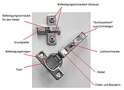
Concealed hinge (components)

Concealed Hinge (Details)

Concealed hinge (assembly)

Concealed hinge (forces when opening and closing)

Cross hinge (principle)

Concealed four-joint hinge (principle)


Another example of a multi-joint hinge is a concealed hinge (see pictures). Concealed hinges are usually four-bar hinges. They are used in furniture construction. Two joints (axes) are arranged in the pot, two others on the lever. The lever ( frame ) and the pot each represent a gear link. The other two gear links (called a belt) connect the axes of the pot and lever.
Concealed hinges enable concealed installation on the piece of furniture (see above). The construction variants are manifold. The axle joints are partially replaced by spring joints (solid joints).
In principle, concealed hinges can be used to create any narrow joints, since the door edges do not collide with neighboring furniture pieces or parts when the door is moved due to the (non-circular) trajectories of the edges (see animation) . However, the manufacturers specify minimum joint widths in the data sheets.
The generation of closing forces with springs is common. In the example, this is done with a leaf spring that is hooked on the lever and on a top axis, whereby it is under tension. When the door is closed, a force is exerted on the four-bar arrangement which keeps the door closed. The door must be opened against the torque exerted by this force. After a certain opening angle, the effect of the spring force on the four-bar changes and now supports the opening or keeps the door open. When closing the door, a torque must first be applied again before the door closes automatically from a certain opening angle. In order to prevent the door from hitting hard, dampers are often built into the hinges.
Like concealed hinges, cross hinges also enable concealed installation. They are intended for butt-closing doors. The functional principle is shown in the picture.
They are five-joint hinges. Two arms (transmission links) are arranged one above the other. Two of the five joints are designed as so-called sliding joints. The axis of a gear element can move in a groove or an elongated hole in another gear element. The paths given by elongated holes or grooves do not necessarily have to be straight.
Usually two pairs of arms placed one on top of the other (i.e. four arms) are used for such hinges, which are often composed of stacked stamped parts (inexpensive to manufacture).
Concealed hinges for butt-closing doors can also be designed as four-bar hinges (see picture).
In addition to furniture construction, multi-joint hinges are also widely used in many other areas (vehicle construction, construction, etc.) in a wide variety of forms.
See also
Web links
Individual evidence
- ↑ hinges in BaunetzWissen.de
- ↑ Duden online: Hinge and cardinal
- ↑ Baunetz_Wissen_Beschläge Scharniere , In: BaunetzWissen.de
- ↑ DIN 18104-2: 2013-05, p. 8.
- ^ August Vormann GmbH: How a hinge is made. January 12, 2014, accessed May 1, 2020 .
- ↑ Poliall rod hinge with joint made of polyurethane . In: PastoreLombardi.com. Accessed May 2020
- ↑ Information sheet "Technical Properties" Poliall hinges , In: PastoreLombardi.com. Accessed May 2020
- ↑ August Huber: Hinge joint that is invisibly attached to furniture. March 15, 1963, accessed on April 3, 2020 (click on "Load complete document" after calling up).
- ^ Paul Hettich: Invisible hinge for furniture or the like. February 16, 1962, accessed on April 3, 2020 (click on "Load complete document" after calling up).
- ^ Paul Hettich: Hinge. November 28, 1962, accessed on March 23, 2020 (click on "Load complete document" after calling up).
- ^ Paul Hettich: Hinge. August 21, 1968, accessed on April 3, 2020 (click on "Load complete document" after calling up).
- ^ Technical drawing according to VSSM. bin-Verlag Dietkon, January 1, 1998, accessed on April 29, 2020 .
- ↑ Christian Bonten: Plastics technology introduction and basics. Hanser Verlag, 2014.
- ↑ Beckmann et al.: Multi-joint hinge. February 2, 2005, accessed on March 20, 2020 (click on "Load complete document" after calling up).
- ^ Franz Hettich: Hinge. July 3, 1962, accessed on April 10, 2020 (click on "Load complete document" after calling up).
- ↑ Dreisewerd: building door and hinge. January 10, 2019, accessed on May 27, 2020 (click on "Load entire document" after calling up).