
Railway coupling: Difference between revisions
No edit summary |
GreenC bot (talk | contribs) Move 1 url. Wayback Medic 2.5 per WP:URLREQ#google.com/patents |
||
| Line 1: | Line 1: | ||
{{Short description|Mechanism for connecting rolling stock in a train}} |
|||
[[Image:Railroad coupler.agr2.jpg|thumb|300px|Knuckle (AAR Type "E") couplers in use]] |
|||
{{Other uses|Coupling (disambiguation)}} |
|||
[[Image:Tow hitch 5.jpg|thumb|right|200px|AAR Type "E" [[railroad car]] coupling]] |
|||
{{train topics}} |
|||
A '''coupling''' (or a '''coupler''') is a mechanism for connecting [[rolling stock]] in a train. The design of these couplings is a standard almost as important as the [[railway gauge]], since flexibility and convenience are maximised if all rolling stock can be coupled together. |
|||
[[File:St Pancras railway station MMB G3 395009.jpg|thumb|250px|[[Scharfenberg coupler]] on a [[Southeastern (train operating company)|Southeastern]] [[British Rail Class 395|Class 395]]]] |
|||
[[File:Scharfenberg coupler in action ICE Leipzig-short.webm|thumb|Video of [[ICE T]] coupling at [[Leipzig Hauptbahnhof]]]] |
|||
A '''coupling''' or '''coupler''' is a mechanism, typically located at each end of a [[rolling stock|rail vehicle]], that connects them together to form a train. The equipment that connects the couplers to the vehicles is the '''draft gear''' or '''draw gear''', which must absorb the stresses of the coupling and the acceleration of the train. |
|||
== Nomenclature == |
|||
Throughout the history of railroading, a variety of coupler designs and types have been developed worldwide. Key design considerations include strength, reliability, easy and efficient handling, and operator safety. Automatic couplers engage automatically when the cars are pushed together. Modern versions not only provide a mechanical connection, but can also couple brake lines and data lines. |
|||
The different types of coupling do not always have formal or official names, which makes descriptions of the couplings in use on any railway system problematic. |
|||
Different countries use different types of couplers. While North American railroads and China use [[Janney coupler]]s, railroads in the former [[Soviet Union]] use [[SA3 coupler]]s and the European countries use [[Buffers and chain coupler|screw couplers]]. Challenges and complications arise when coupling vehicles with different couplers. [[Barrier vehicle|Barrier cars]], also called ''match cars'', cars with [[dual coupling|dual couplers]], or adapters are used to accomplish this task. |
|||
== Buffers and chain == |
|||
==Nomenclature== |
|||
[[Image:European coupler on loco.jpg|thumb|Traditional buffer-and-chain coupler]] |
|||
Compatible and similar couplings or couplers are frequently referred to using widely differing make, brand, or regional names, or nicknames, which can make describing standard or typical designs confusing. Dimensions and ratings noted in these articles are usually of nominal or typical components and systems, though standards and practices also vary widely with railway, region, and era. |
|||
[[Image:Eisenbahn Schraubenkupplung 1.jpeg|thumb|Two cars coupled]] |
|||
[[Image:Chain coupler detail.jpg|thumb|Chain coupler detail (train in shunting mode)]] |
|||
[[Image:Coupler ride mode.jpg|thumb|Cars coupled in ride mode]] |
|||
The standard type of coupling on railways following the British tradition is the buffer and chain coupling used on the pioneering [[Liverpool and Manchester Railway]] of 1830. These couplings followed earlier [[tram]]way practice but were made more regular. The vehicles are coupled by hand using a hook and links with a [[turnbuckle]]-like device that draws the vehicles together. In Britain, this is called a '''screw coupling'''. Vehicles have [[buffer (rail transport)|buffers]], one at each corner on the ends, which are pulled together and compressed by the coupling device. This arrangement limits the slack in trains and lessens shocks. In contrast, [[#Janney coupler|Janney coupler]]s encourage violent encounters in order to engage the coupling fully. The earliest buffers were fixed extensions of the wagon frames, but later spring buffers were introduced. |
|||
Buff: when the consist (one or more cars coupled together) of cars is in compression; opposite of tension.<ref>{{Citation |title=Train Couplers 101 - How do train cars stay together? |url=https://www.youtube.com/watch?v=IEX6_GRk6sU |access-date=2023-04-17 |language=en}}</ref> |
|||
Inefficient and slow, the European system is relatively unsafe because it requires manual coupling between vehicles, exposing workers to the risk of being crushed. With central couplers (except link and pin) it is not usually necessary to get between the cars for coupling or uncoupling. The safety issue was one of the main arguments for changing to central couplers. After more than 30 years, the change has still not been completed; indeed it has barely started.{{Fact|date=March 2008}} |
|||
==Buffers and chain==<!-- Do not remove this because an unknown number of pages still redirect here --> |
|||
This coupling type is the standard in European countries (except the former Soviet Union, where the [[SA3 coupler|SA-3 automatic coupler]] is used). Coupling is done by a worker, who must climb between the cars. First he turns a releasing screw (an aid with two opposite windings, and it does not uncouple the train itself) to the loose position, and then he can hang the chain on the hook. After hanging the chain on the towing hook the releasing screw must be turned to the tight position. When the coupler is uncoupled, it must be hung on the idle hook to prevent damage to itself or the brake pipes. Only shunting is permitted with a dangling chain. Disconnected brake pipes must be hung on hooks. (The picture shows two coupled cars, with a single brake pipe.) |
|||
{{Main|Buffers and chain coupler}} |
|||
The hooks and chain hold the carriages together, while the buffers keep the carriages from banging into each other so that no damage is caused. The buffers can be "dumb" or spring-loaded. That means there are no run-in forces on the coupler. The other benefit compared with automatic couplers is that its lesser slack causes smaller forces on curves; there is a lower probability of a broken coupler in a curve than with automatic couplers. The disadvantage is the smaller mass of the freight that can be hauled by that coupler (maximum 3000 tonnes). |
|||
The basic type of coupling on railways following the British tradition is the buffer and chain coupling. A large chain of three links connects hooks on the adjoining wagons. These couplings followed earlier [[Plateway|tramway]] practice but were made more regular. [[Buffer (rail transport)|Buffer]]s on the frame of the wagon absorbed impact loads, as the train overran a slowing locomotive. |
|||
The simple chain could not be tensioned, and this loose coupling allowed a great deal of back and forth movement and bumping between cars, as well as jarring when trains started. While acceptable for mineral cars, this coupling made for an uncomfortable ride in passenger coaches, so the chain was improved by replacing the center link with a screw with a left-hand thread on one side and a right-hand thread on the other. In the center of the screw is the handle housing with a hinged ball handle attached. This [[turnbuckle]] style arrangement allows the vehicles to be pulled together by tightening the screw with the attached handle. Typically, the screw is tightened until there are two threads left next to the handle housing. A support is attached to the [[trunnion]] nut on the coupling link side to rest the handle of the screw to prevent loosening of the screw while the coupling is in use. The official name of this type of coupling is ''screw coupling'' or ''UIC coupling'' according to the [[European Standard|European standard]] EN 15566 ''Draw gear and screw coupling''. |
|||
Early rolling stock was often fitted with a pair of auxiliary chains as a backup if the main coupling failed. This made sense before the fitting of continuous fail-safe braking systems. |
|||
A simplified version of this, quicker to attach and detach, still used three links but with the centre link given a T-shaped slot. This could be turned lengthwise to lengthen it, allowing coupling, then turned vertically to the shorter slot position, holding the wagons more tightly together. |
|||
On railways where rolling stock always pointed the same way, the chain might be mounted at one end only, as a small cost- and weight-saving method. |
|||
Higher speeds associated with fully-fitted freight{{efn|A train with continuous brakes on all wagons.}} made the screw-tensioned form a necessity. |
|||
On [[rail transport in Germany|German railways]], one buffer is flatter than the other buffer, which is slightly more rounded. This provides better contact between the buffers than would be the case if both buffers were slightly rounded. |
|||
The earliest '[[dumb buffers]]' were fixed extensions of the wooden wagon frames, but later spring buffers were introduced. The first of these were stiff cushions of leather-covered horsehair, later steel springs and then hydraulic damping. |
|||
=== Buffers and narrow gauge === |
|||
This coupling is still widespread in Western and Central Europe and in parts of Northern Africa, the Middle East and South Asia.{{sfn|DAC Report|2020|p=7}} |
|||
With the exception of [[Queensland]] and [[Tasmania]], twin buffers and chains are rare on narrow gauge lines, perhaps because of the buffer locking problem on sharp curves. |
|||
<gallery mode="packed" heights="140px"> |
|||
File:Consett-tankwagon41 - buffer beam.jpg|Three-link coupling on an antique tank wagon |
|||
File:Eisenbahn Schraubenkupplung 1.jpeg|UIC standard screw coupling, shown attached and tightened |
|||
</gallery> |
|||
==Link and pin== |
|||
=== Three-link couplings === |
|||
[[File:Link and Pin.jpg|thumb|left|A link-and-pin coupler]] |
|||
[[File:Early Janney-type AAR coupler.JPG|thumb|Transition era AAR knuckle coupler. The gap in the knuckle accommodates the link of a [[#Link and pin|link and pin coupler]] and the vertical hole in the knuckle accommodates the pin.]] |
|||
[[File:08-130 Esclusas de Miraflores (23).jpg|thumb|Link and pin coupler combined with side buffers on a [[Panama canal mule]].]] |
|||
The link-and-pin coupling was the original style of coupling used on North American railways. After most railroads converted to semi-automatic [[Janney coupler]]s, the link-and-pin survived on [[forest railway]]s. While simple in principle, the system suffered from a lack of standardisation regarding size and height of the links, and the size and height of the pockets. |
|||
The link-and-pin coupler consisted of a tube-like body that received an oblong link. During coupling, a rail worker had to stand between the cars as they came together and guide the link into the coupler pocket. Once the cars were joined, the employee inserted a pin into a hole a few inches from the end of the tube to hold the link in place. This procedure was exceptionally dangerous and many brakemen lost fingers or entire hands when they did not get them out of the way of the coupler pockets in time. Many more were killed as a result of being crushed between cars or dragged under cars that were coupled too quickly. Brakemen were issued with heavy clubs that could be used to hold the link in position, but many brakemen would not use the club, and risked injury. |
|||
A peculiarly British institution was the "loose-coupled" freight train. This used three-link chain couplings with no means of drawing the wagons together: since such trains were not fitted with an automatic through-train braking system there were no pipes to connect between the vehicles. The couplings in the train were kept taut by the last vehicle of the train being a heavily ballasted [[guards van]] with its brakes set slightly on. This helped prevent snapped couplings. Such trains travelled at low speeds and were phased out in the 1970s. {{Fact|date=February 2008}} |
|||
The link-and-pin coupler proved unsatisfactory because: |
|||
An improvement on this is the "Instanter" coupling, in which the middle link of a three link chain is specially shaped so that when lying "prone" it provides enough slack to make coupling possible, but when this middle link is rotated 90 degrees the length of the chain is effectively shortened, reducing the amount of slack without the need to wind a screw. The closeness of the coupling allows the use of inter-vehicle pipes for train brakes. It also has the advantage that it can be operated entirely from the side of the wagons using a shunter's pole and is therefore safer when shunting work is under way. These couplings are still prevalent in UK freight trains today.{{Fact|date=February 2008}} |
|||
* It made a loose connection between the cars, with too much [[slack action]]. |
|||
* There was no standard design, and train crews often spent hours trying to match pins and links while coupling cars. |
|||
* Crew members had to go between moving cars during coupling, and were frequently injured and sometimes killed. |
|||
* The links and pins were often pilfered due to their value as scrap metal, resulting in substantial replacement costs. |
|||
* When a car happened to be turned 180 degrees one would have to look for a link. |
|||
* Railroads progressively began to operate trains that were heavier than the link-and-pin system could cope with. |
|||
In Britain link-and-pin couplers were common on narrow gauge industrial and military railways, and eventually evolved into a form that could be reliably coupled when the train was stationary. |
|||
=== Problems with buffers and chain === |
|||
The buffers and chain coupling system has a maximum load much less that the Janney coupling. Also, on sharp reverse curves, the buffers can get bufferlocked by somehow getting on the wrong side of the adjacent buffer. An accident at a Swiss station was caused by buffer-locked wagons in the 1980s.{{Fact|date=February 2008}} The bufferlock could be caused on the very sharp turnouts by the older rounded buffers. The newer buffers has rectangle shape and they are wider than taller. They are not so flat, so they rarely cause buffer locking.{{Fact|date=February 2008}} |
|||
The [[Panama Canal locks#Mules|Panama Canal mule]]s, the locomotives used to guide the ships through the locks of the [[Panama Canal]], have link and pin couplers and side buffers. This design was chosen so that these normally solo operating locomotives could be coupled to another locomotive in the event of a breakdown. On straight track, the link and pin coupler is used. Since the vertical curve between the straight track sections and the ramp between the lock chambers has a very small radius, the difference in height would be too great for a link and pin coupler, so the locomotives must be pushed through these sections uncoupled by using the side buffers. They have an extra high buffer plate to prevent the buffers from buffer-locking in tight vertical curves. |
|||
=== Variation with gauge === |
|||
[[Image:CH FO HGE44-105-2.JPG|thumb|The narrow gauge "buffer-&-chain" coupler, it's called ''Balancierhebelkupplung'']]The width between the buffers tends to increase as the gauge increases, so that if wagons are changed from one gauge to another, the buffers will no longer match. This occurs because the buffers are originally extensions of the frames, which are spaced according to the gauge. |
|||
{{clear}} |
|||
On some narrow-gauge lines in [[Europe]] a simplified version is used, consisting of a single central buffer with a chain underneath. It's called ''Balancierhebelkupplung''. The chain usually contains a screw-adjustable link to allow close coupling. On sharp curves, a single centre buffer is less likely to be subject to buffer locking problem, as described above. |
|||
== Balance lever coupling == |
|||
{{Main|Balance lever coupling}} |
|||
[[Image:VR Electric Locomotive Helsinki Finland.jpg|thumb|A Finnish locomotive with dual coupling]] |
|||
[[File:20060804S29 22Kupp.jpg|thumb|Balance lever coupling on narrow gauge coach in Switzerland]] |
|||
It is possible to mount both buffers and chain and knuckle couplers on the same car, provided that one can swing out of the way. |
|||
The balance lever coupling, also central buffer coupling with two screw coupling, is a coupler commonly used on narrow gauge railroads with tight curves. By swapping the pulling and pushing devices, the standard screw coupling used on standard gauge railroads became a center buffer coupling with one screw coupling on each side of the buffer. The screw couplers are connected to a compensating lever that pivots on a vertical trunnion on the center buffer rod, allowing an even distribution of tractive forces between the two screw couplers.<ref>Bruno Lämmli: [https://www.lokifahrer.ch/Lukmanier/Rollmaterial/Kupplung/Zug-Druck.htm ''Zug- / Stossvorrichtung.''] Auf: ''Lokifahrer,'' 2021.</ref> |
|||
==Albert coupler== |
|||
Locomotives and some freight cars of the Indian Railways are fitted with a 'transition coupler' that incorporates a screw coupling within a knuckle coupler: the knuckle coupler remains in position and does not swing away when not in use. The screw coupling is mounted on a lug within the knuckle coupler. See [http://www.ba-bautzen.de/wirtschaftssenioren/amk/amkenglish/wabconeu_e.htm SAB WABCO C-AK]. Most Indian freight cars use the knuckle coupler alone, without buffers, whereas passenger coaches almost exclusively use screw couplers and buffers. Exceptions are the new LHB coaches imported from Europe, and a few other makes of carriages converted to use knuckle couplers. [http://irfca.org/faq/faq-stock2.html] |
|||
[[File:Strassenbahn Albertkupplung.jpeg|thumb|Albert coupler on a European tram]] |
|||
To avoid safety issues, Karl Albert, then director at the [[Trams in Krefeld|Krefeld Tramway]], developed the '''Albert coupler''' during 1921. The Albert coupler was created as a key and slot coupler with two pins. Vehicles to be coupled were pushed together, both couplings moving to the same side. One pin was inserted, then the vehicles were pulled to straighten the coupling and the other pin inserted. This operation required less exact shunting. Due to the single-piece design, only minimal slack was possible. The system became quite popular with tram systems and narrow gauge lines. |
|||
During the 1960s most cities replaced them with automatic couplers. But even in modern vehicles, Albert couplers get installed as emergency couplers for towing a faulty vehicle. |
|||
[[Image:GNER-91116-coupling-01.jpg|thumb|British-style dual buffer-and-chain/automatic coupler with knuckle swung out of the way]]Some Russian locomotives and wagons have buffers together with the central coupler. When coupling to Finnish equipment, a short chain with a block that fits in the central coupler is placed on the Russian side, backing up and compressing the buffers so that the chain can be laid on the hook. (That is also the common way of coupling locomotives to or from wagons, faster than unscrewing the link.) |
|||
==Miller hook and platform== |
|||
British locomotive-hauled passenger carriages adopted a dual coupling system in the 1950s. They have retractable buffers and a central '''Buckeye''' automatic knuckle coupler that lowers to reveal a hook for a screw-type chain coupling. Inter-stock coupling was with the automatic coupler (with the buffers retracted), while connection to the locomotive was with the buffer-and-chain system with a screw coupler. |
|||
The link and pin was replaced in North American passenger car usage during the latter part of the 19th century by the assemblage known as the [[Miller platform]], which included a new coupler called the Miller hook.<ref>[https://3.bp.blogspot.com/-DfQAzcJxZd4/WeSz7ATgcRI/AAAAAAAAcXA/tlA82fwwJoQp_hxaQU7DjGp8iLcHfUhAQCLcBGAs/s1600/C17%2B534%2B%25281280x960%2529.jpg Miller Hook]</ref> The Miller platform (and hook coupler) was used for several decades before being replaced by the [[Janney coupler]]. |
|||
== |
==Norwegian== |
||
{{Main|Norwegian coupling}} |
|||
[[Image:Link and pin coupler pocket.jpg|thumb|The coupler pocket (just below the two lights) for a link and pin coupler on a 15 [[inch]] (381 [[millimetre|mm]]) [[rail gauge|gauge]] [[speeder]].]] |
|||
[[File:URCengines.jpg|right|thumb|Norwegian coupling in [[Uganda Railways Corporation|Uganda]]]] |
|||
The '''link and pin''' coupling was the original style of coupling used on American railways, surviving after conversion to Janney couplings on forestry railways. While simple in principle, the link and pin coupling suffered from a lack of standardisation regarding size and height of the links. |
|||
The Norwegian coupler consists of a central buffer with a movable hook that drops into a slot in the central buffer.<ref name="nw">{{cite web|url=http://members.ozemail.com.au/~telica/Norway_Setesdalsbanen.html|title=Setesdals Railway|website=Members.ozemail.com.au|access-date=2016-04-08|archive-date=2016-03-04|archive-url=https://web.archive.org/web/20160304072613/http://members.ozemail.com.au/~telica/Norway_Setesdalsbanen.html|url-status=dead}}</ref> There may also be a U-shaped safety catch on the opposite buffer that is flipped over the top of the hook to secure it. The safety device may also be a chain with a ball-shaped weight at the end that is thrown over the hook to hold it in place.<ref name="nw"/> On railways where the rolling stock always face the same direction, the mechanical hook can be on one end of the wagon only. Not all Norwegian couplers are compatible with one another as they vary in height and width, and may or may not be limited to one hook at a time. The traction force limit is typically 350 kN.<ref>{{cite web |title=Lloyd MCA-PH |url=https://laf-lloyd.com/en/lloyd-mca-ph/ |website=LAF}}</ref> Sometimes the Norwegian coupler is supplemented with auxiliary chains. |
|||
The link and pin coupler consisted of a tubelike body that received an oblong link. During coupling, a railworker had to stand between the cars as they came together and guide the link into the coupler pocket. Once the cars were joined, the employee inserted a pin into a hole a few inches from the end of the tube to hold the link in place. This procedure was exceptionally dangerous and many brakemen lost fingers or entire hands when they did not get their hands out of the way of the coupler pockets; many more were killed as a result of being crushed between cars or dragged under cars that were coupled too quickly. Brakemen were issued with heavy clubs that could be used to hold the link in position, but many brakemen would not use the club, and risk injury. |
|||
The Norwegian coupler is also known as the Lloyd coupler named after its British manufacturer F.H. Lloyd & Co. Ltd near [[Wednesbury]] or as the meat chopper coupler named after the shape of the movable hook. The Norwegian coupler allows sharper curves than the buffer and chain coupler, which is an advantage on [[narrow gauge railway]]s where low speeds and reduced train loads allow a simpler system. The Norwegian coupler is found only on [[narrow gauge railway]]s of {{RailGauge|1067mm|lk=on}}, {{RailGauge|1000mm|lk=on}} or less in [[Great Britain]] and its former colonies. For example, it is used on the [[Isle of Man Railway]], the [[Western Australian Government Railways]], in [[Tanzania]], on the [[Ffestiniog Railway]], on the [[Lynton and Barnstaple Railway]], and on the [[Welsh Highland Railway]], |
|||
The link and pin coupler proved unsatisfactory because: |
|||
{{Clear}} |
|||
* It made a loose connection between the cars, with too much [[slack action]]. |
|||
* There was no standard design, and train crews often spent hours trying to match pins and links while coupling cars. |
|||
* The links and pins were often pilfered (due to their value as scrap metal), resulting in substantial replacement costs. John H. White suggests that the railroads considered this to be more important than the safety issue at the time (see reference below). |
|||
* Crew members had to go between moving cars during coupling, and were frequently injured and sometimes killed. |
|||
* Eventually, railroads wished to operate trains that were heavier than the link and pin system could cope with. |
|||
==Radial couplers== |
|||
An episode of the 1960s TV series ''[[Casey Jones]]'' was devoted to the problems of link and pin couplings. |
|||
Two versions of radial coupler were used in South Africa. One, the Johnston coupler, commonly known as a bell link-and-pin coupler, was introduced in 1873 and is similar in operation to and compatible with [[#Link and pin|link-and-pin]] couplers, but bell-shaped with a circular coupler face. The other, the bell-and-hook coupler, was introduced in 1902 and is similar to the [[#Norwegian|Norwegian coupler]], but also with a circular coupler face and with a coupler pocket which is open at the top of the coupler face to accommodate the drawhook.<ref name="Trokhandboek">Suid-Afrikaanse Vervoerdienste (South African Transport Services) (1983). ''Passassierswa- en Trokhandboek (Passenger Carriage and Truck Manual), Vol 1, Hoofstukke 1-15 (Chapters 1-15)''. South African Transport Services, 1983. Chapter 13.</ref> |
|||
===Johnston coupler=== |
|||
==Norwegian== |
|||
[[File:Early Janney-type AAR coupler.JPG|thumb|Transition era AAR knuckle coupler. The gap in the knuckle accommodates the link of a [[#Johnston coupler|Johnston coupler]] and the vertical hole in the knuckle accommodates the pin.]] |
|||
[[Image:Alco.jpg|300px|right|thumb|Norwegian coupling fitted to an ex-[[War Department Light Railways|WDLR]] Alco at the [[Ffestiniog Railway]]]] |
|||
The Johnston coupler, commonly known as a bell link-and-pin coupler from its bell shape, was first introduced in the [[Cape Colony|Cape of Good Hope]] in 1873, following the establishment of the [[Cape Government Railways]] (CGR) in 1872 and the decision by the Cape government to expand the railways into the interior and to [[Track gauge conversion|convert]] the existing tracks from {{Track gauge|56.5in|allk=on}} to {{Track gauge|42in|lk=on}} Cape gauge. All new Cape gauge locomotives and rolling stock acquired from 1873 were equipped with these or similar couplers, beginning with the [[CGR 0-4-0ST 1873|CGR 0-4-0ST of 1873]], a construction locomotive named ''Little Bess''.<ref name="SAR History">{{cite book| title=The South African Railways - Historical Survey| editor=George Hart| publisher=Bill Hart, Sponsored by Dorbyl Ltd.| year=1978| pages=9, 11–13}}</ref><ref name="Holland 2">{{Holland-Vol 2|pages=51-52, 117-118}}</ref><ref name="Paxton-Bourne">{{Paxton-Bourne|pages=6, 110-112, 156-157}}</ref> |
|||
[[Image:URCengines.jpg|300px|right|thumb|Norwegian coupling from Uganda]] |
|||
[[File:Johnston link-and-pin coupler.jpg|thumb|left|Johnston link-and-pin coupler]] |
|||
'''Norwegian''' (or '''meat chopper''') couplings consist of a central buffer with a mechanical hook that drops into a slot in the central buffer. The Norwegian is found only on [[narrow gauge railway]]s {{Fact|date=December 2007}}, such as the [[Ffestiniog Railway]] and the [[Welsh Highland Railway]], where low speeds and reduced train loads allow a simpler system. On railway lines where rolling stock always points the same way, the mechanical hook may be provided only on one end of each wagon. This was the situation on the [[Lynton and Barnstaple Railway|Lynton & Barnstaple]] (L&B), a narrow gauge line in [[Devon]], [[England]], and still applies to railways in [[New Zealand]]. Similarly, the hand brake handles may also be on one side of the wagons only. |
|||
The [[Natal Government Railways]] (NGR), established in the [[Colony of Natal]] in 1875, followed suit and all locomotives and rolling stock acquired by that railway were equipped with Johnston couplers, beginning with the [[NGR Class K 2-6-0T]] in 1877.<ref name="Holland 1">{{Holland-Vol 1|pages=84-87, 109-112}}</ref><ref name="SAR&H May 1944">Espitalier, T.J.; Day, W.A.J. (1944). ''The Locomotive in South Africa - A Brief History of Railway Development. Chapter III - Natal Government Railways''. South African Railways and Harbours Magazine, May 1944. pp. 337-340.</ref> |
|||
Likewise, in 1889, when the first locomotives were obtained by the newly established [[Netherlands-South African Railway Company]] in the [[South African Republic|''Zuid-Afrikaansche Republiek'']], they were fitted with Johnston couplers.<ref name="Holland 2"/><ref name="SAR&H Oct 1944">Espitalier, T.J.; Day, W.A.J. (1944). ''The Locomotive in South Africa - A Brief History of Railway Development. Chapter IV - The N.Z.A.S.M.''. South African Railways and Harbours Magazine, October 1944. pp. 762, 764.</ref> |
|||
Norwegian couplings are not particularly strong, and may be supplemented by auxiliary chains. The L&B originally used side chains in conjunction with Norwegian couplers, but these were found to be unnecessary with the slow speeds employed (10-15 miles per hour) and were removed within a year or so of the line opening in 1898. |
|||
Unlike the {{Track gauge|24in|lk=on}} narrow gauge railways of the CGR, those of the NGR also made use of Johnston couplers. The first of these narrow gauge lines came into operation in 1906, when the first [[NGR Class N 4-6-2T 1906|NGR Class N 4-6-2T]] locomotives entered service on the [[Weenen]] branch out of [[Estcourt]].<ref name="Paxton-Bourne"/><ref name="SAR&H Sep 1944">Espitalier, T.J.; Day, W.A.J. (1944). ''The Locomotive in South Africa - A Brief History of Railway Development. Chapter III - Natal Government Railways'' (Continued). South African Railways and Harbours Magazine, September 1944. p. 669.</ref> |
|||
The [[Pichi Richi Railway]] in [[South Australia]] uses Norwegian couplers as its standard, and converts Janney coupler to Norwegian as required. The slot in the "buffer beam" where the coupler protrudes appears to be about the same for both types of couplers. As a museum, it is appropriate to use the older type of coupling. |
|||
Coupling and uncoupling were done manually, which posed a high risk of serious injury or death to crew members, who had to go between moving vehicles to guide the link into the coupler pocket during coupling. Johnston couplers gradually began to be replaced on the [[South African Railways]] from 1927, but not on narrow gauge rolling stock. All new Cape gauge locomotives and rolling stock acquired from that year were equipped with [[Janney coupler|AAR knuckle]] couplers. Conversion of all older rolling stock was to take several years and both coupler types could still be seen on some vehicles into the late 1950s. During the transition period, knuckle couplers on many locomotives had a horizontal gap and a vertical hole in the knuckle itself to accommodate, respectively, a link and a pin, to enable it to couple to vehicles which were still equipped with the older Johnston couplers.<ref name="Holland 2"/><ref name="Diagram-book 2">South African Railways & Harbours/Suid Afrikaanse Spoorweë en Hawens (15 Aug 1941). ''Locomotive Diagram Book/Lokomotiefdiagramboek, 2′0″ & 3′6″ Gauge/Spoorwydte, Steam Locomotives/Stoomlokomotiewe''. SAR/SAS Mechanical Department/Werktuigkundige Dept. Drawing Office/Tekenkantoor, Pretoria. pp. 6a-7a, 25.</ref> |
|||
===Bell-and-hook coupler=== |
|||
Not all Norwegian couplings are compatible with one another as they vary in height, width, and may or may not be limited to one hook at a time. |
|||
The bell-and-hook coupling system was first introduced in the Cape of Good Hope in 1902, when two [[CGR Type A 2-6-4T]] locomotives were acquired as construction engines on the new {{Track gauge|2ft|lk=on}} narrow gauge [[Avontuur Railway]] which was being constructed out of [[Port Elizabeth]] through the [[Langkloof]]. In South Africa, these couplers were used on only the narrow gauge lines in the Cape of Good Hope.<ref name="Trokhandboek"/><ref name="Paxton-Bourne"/><ref name="SAR&H Apr 1944">Espitalier, T.J.; Day, W.A.J. (1944). ''The Locomotive in South Africa - A Brief History of Railway Development. Chapter II - The Cape Government Railways'' (Continued). South African Railways and Harbours Magazine, April 1944. pp. 253-257.</ref><ref name="Dulez 150">{{Dulez 150|page=232}}</ref> |
|||
The coupler is similar to the [[Norwegian coupling|Norwegian coupler]]. It is a radial coupler with a coupler pocket which is open at the top of the coupling face. Instead of a link and pins, it makes use of a drawhook which, upon coupling, slides over the drawhook pin in the coupler of the next vehicle in the train. To prevent the drawhook of the mating coupler from accidental uncoupling, the coupler bell is equipped with a drawhook guard, commonly known as a bridle, above the coupler pocket.<ref name="Trokhandboek"/> |
|||
== Automatic couplers == |
|||
There are a number of automatic train couplings, most of which are mutually incompatible. |
|||
* '''AAR ([[American Association of Railroads]])''' coupler (also known as '''knuckle coupler''' and once known as '''Janney coupler''', '''alliance coupler''', see below) used in [[Rail transport in Canada|Canada]], the [[Rail transport in the United States|USA]], [[Mexico]], [[Rail transport in Japan|Japan]], [[Rail transport in Australia|Australia]], [[South Africa]], [[Saudi Arabia]], [[Cuba]], [[Chile]], [[Brazil]], [[Rail transport in the People's Republic of China|China]] and elsewhere. |
|||
** Maximum tonnage as high as 32,000 t. such as [[Fortescue Metals Group|Fortescue Railway]]. |
|||
** Drawbar pull tractive effort rated with a minimum strength 350000 lb. (approx. 159 t.) for general service coupler made of Grade B steel. Grade E knuckles may have an ultimate strength of 650,000 lb. (approx. 300 t.) |
|||
** The AAR (Janney) couplers comes in at least two sizes, "full size" and "three quarter", which are not compatible. Lighter weight railways, especially those of narrow gauge or with no need for interrunning sometimes use smaller (3/4 or half size) versions of the AAR coupling. |
|||
** AAR couplers are always right-handed. |
|||
** AAR are not necessarily mounted at the same height above rail - some variation can be tolerated. |
|||
** AAR couplers are uncoupled by lifting the coupling pin with a lever at the corner of the car. This pin is locked when the coupler is under tension, so the usual uncoupling steps are to compress the coupling with a locomotive, lift and hold up the pin, then pull the cars apart. Side operated variants are called the "'''Sharon coupler'''" or "'''Buckeye coupler'''" [http://www.wsr.org.uk/couplings.htm]. |
|||
** Trains fitted with AAR couplers can have heavier loads than any other type of coupler. Thus the heaviest coal trains in [[New Zealand]] have AAR couplings even though the remainder of the fleet has the '''meatchopper''' kind. Also, long-distance freight trains in [[North America]] are quite commonly more than a mile (1.6 km) long, whereas this is unknown in [[Europe]], where most freight trains still use the '''buffers and chain''' system. |
|||
** See also "'''Janney Coupler'''" and "'''changes since 1873'''" below. |
|||
* [[Russia]]n [[SA3 coupler]] , also known as a "[[Willison Coupler]] with a Russian contour", (somewhat similar to Janney) used in [[Russia]], former [[Soviet Union]], [[Finland]], [[Mongolia]], [[Iraq]] and on [[Malmbanan]], [[Sweden]]. See also: [http://railways.id.ru/glossary/avtoscepka.html Animation showing SA3 coupling] (site in Russian) |
|||
** Russian trains are rarely longer than about 750 m and rarely exceed a maximum tonnage about 6,000 t, so it is not clear what potential load these couplings are capable of. |
|||
** The effort to break the SA-3 coupler is about 300 t. |
|||
** Maximum allowed tractive effort to the SA-3 is limited to 135 t. by Russian white papers. |
|||
** [[Malmbana]] trains are about 8,000T. |
|||
* [http://www.ba-bautzen.de/wirtschaftssenioren/amk/amkenglish/wabconeu_e.htm European proposal coupler ], (compatible with the Russian coupler) with automatic air, control and power connections. Implementation permanently delayed except for a few users. |
|||
* '''Scharfenberg coupler''' used on electric passenger trains - connects brake and controls. See '''Fully Automatic Couplings''' below. |
|||
** Maximum tonnage under 1,000 t. |
|||
* Note: There are a number of other automatic train couplings similar to the Scharfenberg coupler, but not necessarely compatible with it. Older US transit operators continue to use these non-Janney electro-pneumatic coupler designs and have used them for decades. |
|||
Usual practice was to have a drawhook fitted to only one of the mating couplers and train crews therefore carried spare drawhooks and drawhook pins on the locomotive. While automatic coupling is possible, this rarely happens and manual assistance is required during coupling. Uncoupling is done manually by lifting the drawhook by hand to release it. The coupler could be adapted to be compatible with the Johnston coupler by replacing the drawhook with a U-shaped adapter link, which was attached using the same drawhook pin.<ref name="Trokhandboek"/> |
|||
=== Janney coupler === |
|||
Later '''[[Master Car Builders Association]] coupler''', now '''AAR ([[American Association of Railroads]]) coupler''', see also '''AAR coupler''' above. |
|||
[[Image:Railroad coupler diagram.jpg|thumb|250px|Diagram of the top view of Janney's coupler design as published in his patent application in [[1873]].]] Janney couplings are always right-handed. |
|||
Bell-and-hook couplers began to be replaced on the [[Avontuur Railway]] upon the introduction of [[South African Class 91-000|Class 91-000]] diesel-electric locomotives on the narrow gauge system in 1973. All new narrow gauge rolling stock acquired for that line from that year were equipped with [[SA3 coupler|Willison couplers]]. Older rolling stock were not converted and an adapter was used to enable coupling between the two types. The drawhook on the bell-and-hook coupler would be replaced with the adapter, which was attached using the same drawhook pin.<ref name="Trokhandboek"/> |
|||
The '''knuckle coupler''' or '''Janney coupler''' was invented by '''[[Eli H. Janney]]''', who received a [[patent]] in 1873 ({{US patent|138405}}). It is also known as a "buckeye coupler", notably in the [[United Kingdom]], where some rolling stock (mostly for passenger trains) is fitted with it. Janney was a dry goods clerk and former [[Confederate Army]] officer from [[Alexandria, Virginia]], who used his lunch hours to whittle from wood an alternative to the '''link and pin coupler'''. |
|||
<gallery mode="packed" neights="140px"> |
|||
File:Bell-and-hook coupler.jpg|left|Bell-and-hook coupler |
|||
File:Bell-and-hook coupler & Willison adapter.jpg|Bell-and-hook coupler with Willison adapter |
|||
File:Willison adapter b.jpg|left|Willison coupler adapter for bell-and-hook couplers |
|||
File:Bell-and-hook coupler & Johnston adapter.jpg|Bell-and-hook coupler with Johnston coupler adapter link instead of a hook |
|||
</gallery> |
|||
==Automatic couplers== |
|||
In 1893, satisfied that an automatic coupler could meet the demands of commercial railroad operations and, at the same time, be manipulated safely, the [[United States Congress]] passed the [[US Railroad Safety Appliance Act|Safety Appliance Act]]. Its success in promoting switchyard safety was stunning. Between 1877 and 1887, approximately 38% of all railworker accidents involved coupling. That percentage fell as the railroads began to replace link and pin couplers with automatic couplers. By 1902, only two years after the SAA's effective date, coupling accidents constituted only 4% of all employee accidents. Coupler-related accidents dropped from nearly 11,000 in 1892 to just over 2,000 in 1902, even though the number of railroad employees steadily increased during that decade. |
|||
There are a number of automatic train couplings, most of which are mutually incompatible. The level of automation varies and can be divided into categories: |
|||
* mechanical coupling of vehicles only, requires manual connection of pneumatic and electrical lines; |
|||
* mechanical coupling of vehicles with automatic connection of pneumatic lines, requires manual connection of electrical lines; |
|||
* mechanical coupling of vehicles with automatic connection of pneumatic and electrical lines (but not data transmission lines); |
|||
* mechanical coupling of vehicles with automatic connection of pneumatic and electrical lines (including data transmission lines); |
|||
* mechanical coupling of vehicles with automatic connection of pneumatic and electrical lines (including data transmission lines) and automatic uncoupling capability.{{sfn|DAC Report|2020|p=13}} |
|||
=== Buckeye/Janney/MCB/ARA/AAR/APTA couplers === |
|||
When the Janney coupling was chosen to be the American standard, there were 8000 patented alternatives to choose from. |
|||
{{Main|Janney coupler|Tightlock coupling}} |
|||
[[File:Syracuse-malleable 1899.jpg|left|thumb|[[Syracuse Malleable Iron Works]] – 1894. The gap in the knuckle accommodates the link of a [[Coupling (railway)#Link and pin|link and pin coupler]] and the vertical hole in the knuckle accommodates the pin. This design was used in the transition period.]] |
|||
[[File:Railroad coupler.agr2.jpg|thumb|right|Knuckle (AAR Type "E") couplers in use]] |
|||
[[File:Janney coupler drawing.png|thumb|right|Diagram of the top view of Janney's coupler design as published in his patent application in 1873]] |
|||
[[File:Northern-321901-coupling-02.jpg|left|thumb|[[American Public Transportation Association|APT]] [[Tightlock coupling|Type H Tightlock coupler]] on [[British Rail Class 321]].<br>Lower electric connector is not typical in North America.]] |
|||
The Janney coupler, later the Master Car Builders Association (MCB) coupler,<ref name=MCB>{{cite web|url=https://archive.org/search.php?query=creator%3A%22Master%20Car-Builders'%20Association%22 |title=Internet Archive Search: creator:"Master Car-Builders' Association" |website=Archive.org |access-date=2016-04-08}}</ref> now the [[Association of American Railroads]] (AAR) coupler, is also commonly known as a ''buckeye'', ''knuckle'', or ''Alliance'' coupler. The AAR/APTA TypeE, TypeF, and TypeH couplers are all compatible Janney couplers, but used for different rail cars (general freight, tank cars, rotary hoppers, passenger, etc.). |
|||
The knuckle coupler or Janney coupler was invented by [[Eli H. Janney]], who received a [[patent]] in 1873 ({{US patent|138405}}).<ref>{{cite web|url=http://inventors.about.com/library/inventors/bljannycoupler.htm|title=Eli Janney - The Janney Coupler|website=Inventors.about.com|access-date=2016-04-08|archive-date=2008-11-06|archive-url=http://webarchive.loc.gov/all/20081106171853/http://inventors.about.com/library/inventors/bljannycoupler.htm|url-status=dead}}</ref> It is also known as a ''buckeye coupler'', notably in the United Kingdom, where some rolling stock (mostly for passenger trains) is fitted with it. Janney was a dry goods clerk and former [[Confederate Army]] officer from [[Alexandria, Virginia]], who used his lunch hours to whittle from wood an alternative to the link and pin coupler. The term ''buckeye'' comes from the nickname of the US state of [[Ohio]], the "Buckeye State" and the Ohio Brass Company which originally marketed the coupling.<ref name="aec">{{cite web|url=http://www.aecinfo.com/1/company/09/17/09/company_1.html |title=Ohio Brass Co. Company Profile on |website=Aecinfo.com |access-date=2016-04-08}}</ref><ref name="brass">{{cite web|url=http://www.rootsweb.ancestry.com/~ohrichla/PofP/Leaf/OhioBrass.pdf |title=Ohio Brass Started As Small Jobbing Foundry In 1888 |website=Rootsweb.ancestry.com |access-date=2016-04-08}}</ref> |
|||
The only significant defect of the AAR (Janney) design is that sometimes the drawheads need to be manually aligned. |
|||
In 1893, satisfied that an automatic coupler could meet the demands of commercial railroad operations and, at the same time, be manipulated safely, the [[United States Congress]] passed the [[US Railroad Safety Appliance Act|Safety Appliance Act]]. Its success in promoting switchyard safety was stunning. Between 1877 and 1887, approximately 38% of all railworker accidents involved coupling. That percentage fell as the railroads began to replace link and pin couplers with automatic couplers. By 1902, only two years after the SAA's effective date, coupling accidents constituted only 4% of all employee accidents. Coupler-related accidents dropped from nearly 11,000 in 1892 to just over 2,000 in 1902, even though the number of railroad employees steadily increased during that decade. |
|||
=== Changes since 1873 ===<!-- This section is linked from [[Buckeye]] --> |
|||
[[Image:SMS 301-coupler.jpg|thumb|250px|Standard ARR Type E couplers doing their job on a freight train.]] |
|||
The AAR coupler has stood the test of time since its invention, and has seen only minor changes: |
|||
* It is clear that the original Janney coupler is no longer compatible with the latest AAR couplers. A visual comparison between the original Janney contour and the current AAR contour (see the illustration of the "'''Diagram of the top view of Janney's coupler...'''" and the photograph of the "'''Knuckle couplers in use'''" elsewhere in this article) would strongly indicate that the original Janney contour and the current AAR contour (especially that of the knuckle itself) are no longer compatible. The current AAR contour dates back to the "[[Master Car Builders Association]] (MCBA)" coupler. |
|||
* Buckeye coupler, a side operated version of the MCBA coupler [http://www.wsr.org.uk/couplings.htm] |
|||
* Type "E" coupler, the original (plain) AAR coupler, derived from the Master Car Builders Association coupler. |
|||
* Type "F" coupler, a "Tooth and socket" variation to prevent accidents, derailments and wrecks from uncoupling the couplers. The "tooth" on a loose coupler could puncture any [[tank car]] or other car carrying hazardous materials. Variations on the AAR type "F" coupler have been devised to provide extra protection, in case of derailments and train wrecks, to cars routinely carrying sensitive or hazardous loads. These variations of type "F" couplers, generally involving "shelves", remain fully compatible with standard AAR couplers, but tend to keep derailments and collisions from uncoupling the cars (thereby preventing the "tooth" of the couplers from piercing the ends of the cars). |
|||
* The APTA (former AAR) standard type "H" coupler, a "Tooth and socket" variation used mostly, if not exclusively, on passenger cars. Types "F" and "H" couplers are also known as [[tightlock coupling]]s. The Type "H" coupler is now under the supervision of the APTA ([[American Public Transportation Association]]) |
|||
* "pads" to reduce slack on passenger trains. |
|||
* improvement to castings, etc. to increase maximum trailing load. |
|||
* rotating-shaft couplers (type "F") introduced for use in [[rotary car dumper]]s such as on the [[Pilbara]] railways. |
|||
* narrow gauge railways such as the [[Victoria (Australia)|Victorian]] [[Puffing Billy Railway]] use a miniature version of the AAR coupler. |
|||
When the Janney coupler was chosen to be the North American standard, there were 8,000 patented alternatives to choose from. Many AAR coupler designs exist to accommodate requirements of various car designs, but all are required to have certain dimensions in common which allow for one design to couple to any other.<ref name="AAR MRSP:SIII">AAR Manual of Standards and Recommended Practices, Section S, Part III:Coupler and Yoke Details, Issue 06/2007</ref> |
|||
== Fully automatic couplings == |
|||
Fully automatic couplings are those that make all connections between the rail vehicles (mechanical, air brake and electrical) without human intervention, in contrast to autocouplers which just handle the mechanical aspects. The majority of trains fitted with these types of couplers are multiple units, especially those used in [[mass transit]] operations. |
|||
The Janney coupler is used in the [[Rail transport in the United States|United States]], [[Rail transport in Canada|Canada]], [[Rail transport in Mexico|Mexico]], [[Rail transport in Japan|Japan]], [[Rail transport in India|India]], [[Rail transport in Taiwan|Taiwan]], [[Rail transport in Australia|Australia]], [[Rail transport in New Zealand|New Zealand]], [[Rail transport in South Africa|South Africa]], [[Rail transport in Saudi Arabia|Saudi Arabia]], [[Rail transport in Cuba|Cuba]], [[Rail transport in Chile|Chile]], [[Rail transport in Brazil|Brazil]], [[Rail transport in Portugal|Portugal]], [[Rail transport in the People's Republic of China|China]] and many countries in Africa both standard gauge and narrow gauges. |
|||
There are a few designs of fully automatic couplers in use worldwide, including the Scharfenberg coupler, various knuckle hybrids (such as the Tightlock, used in the UK), the wedgelock coupling, Dellner couplings (similar to Scharfenberg couplers in appearance), and the BSI coupling. |
|||
The Janney coupler generally provides only mechanical coupling, only Type H adds automatic connections of pneumatic and electrical lines.{{sfn|DAC Report|2020|p=30–31}} |
|||
Older US transit operators use non-Janney electro-pneumatic coupler designs that have been in service for decades. |
|||
{{clear}} |
|||
====Changes since 1873==== |
|||
{{Main|Janney coupler#Changes since 1873|l1=Janney coupler § Changes since 1873}} |
|||
====Bazeley coupler==== |
|||
<gallery> |
|||
{{Main|Janney coupler#Bazeley Coupler|l1=Janney coupler § Bazeley coupler}} |
|||
Image:Northern-333011-coupling.jpg|Dellner manufactured Scharfenberg |
|||
Image:ICE3_Scharfenberg_coupling_detail_view.jpg|Scharfenberg |
|||
====Henricot coupler==== |
|||
Image:Northern-144023-coupling-01.jpg|BSI |
|||
{{Main|Janney coupler#Henricot coupler|l1=Janney coupler § Henricot coupler}} |
|||
Image:Northern-321901-coupling-02.jpg|APTA, Type "H", [[Tightlock coupling]] |
|||
Image:London Underground 1996ts.jpg|Wedgelock |
|||
The Henricot coupler is a variation on the Janney coupler, introduced by Belgian engineer and entrepreneur {{ill|Émile Henricot|fr|Émile Henricot}} of [[Court-Saint-Étienne]]. It is used on certain EMUs of the [[National Railway Company of Belgium]], including the {{ill|Belgian Railways Class 75|lt=Class 75|fr|Automotrice AM75}}). |
|||
Image:SEPTA_budd-coupler.jpg|[[Budd Company|Budd]] Pin and cup coupler |
|||
{{-}} |
|||
<gallery mode="packed" heights="150px" caption="Henricot couplers"> |
|||
Image:AM75 Série 800 SNCB.jpg|Henricot coupler on an [[NMBS/SNCB class 75|SNCB Class 75]] EMU with separate [[Railway air brake|air brake]] and [[head-end power]] connections |
|||
File:Attelage Henricot.jpg|Henricot coupler on a [[Belgian Railways Classical twin EMUs|Belgian EMU]] |
|||
File:NMBS 837.JPG|Closeup of Henricot coupler |
|||
</gallery> |
</gallery> |
||
===Willison/SA3 coupler=== |
|||
{{Main|SA3 coupler}} |
|||
[[File:Scepka.GIF|thumb|right|The simplified scheme of the SA-3 automatic couplers.<br>[[:File:Sa3.gif|An animation of the SA-3 coupler]]]] |
|||
[[File:Class 91-000 no. 91-004 Willison coupler.jpg|thumb|Willison coupler on South African {{Track gauge|2ft|lk=on}} narrow gauge]] |
|||
The Willison coupler was developed in the US in 1916 to address issues present in the Janney coupling.{{sfn|DAC Report|2020|p=19}} |
|||
The Russian SA3 coupler works according to the same principles as the AAR coupler but the two types are incompatible.<ref>{{cite web |url=http://railways.id.ru/glossary/avtoscepka.html |title=ДЖД - Толковый словарь |website=Railways.id.ru |date=2005-05-16 |access-date=2016-04-08 |archive-date=2014-04-26 |archive-url=https://web.archive.org/web/20140426201414/http://railways.id.ru/glossary/avtoscepka.html |url-status=dead }}</ref> It was introduced in the Soviet Union in 1932 based on a British patent and has since been used on the whole {{Track gauge|1520mm|lk=on}} network, including [[Rail transport in Mongolia|Mongolia]]. [[Rail transport in Finland|Finnish]] locomotives have Unilink couplers that can couple to UIC couplers used in Finnish stock and SA3 couplers used in Russian stock. |
|||
It is also used on the {{Track gauge|sg|allk=on}} networks of [[Rail transport in Iran|Iran]] and on [[Malmbanan]] in Sweden for ore trains. Some {{Track gauge|2ft|lk=on}} gauge cane tramway vehicles in [[Rail transport in Queensland|Queensland]] have been fitted with miniature Willison couplers.<ref>[[Light Railways]], October 2013, p. 23</ref> It was introduced on the {{Track gauge|2ft}} narrow gauge [[Avontuur Railway]] of the South African Railways in 1973.<ref name="Trokhandboek"/> |
|||
* Russian trains are rarely longer than about {{convert|750|m|0|abbr=on}}{{Citation needed|date=January 2011}} and rarely exceed a maximum tonnage of about {{convert|6000|t|abbr=on|lk=on}}{{Citation needed|date=January 2011}}. The heaviest trains using these couplers are on [[Malmbanan]] where they are up to {{convert|9000|t|abbr=on}}.<ref>{{Cite web |url=http://m.railjournal.com/index.php/freight/sweden-introduces-325-tonne-axleloads-on-iron-ore-line.html |title=Sweden introduces 32.5-tonne axleloads on Iron Ore Line |access-date=2017-10-29 |archive-date=2017-10-29 |archive-url=https://web.archive.org/web/20171029173006/http://m.railjournal.com/index.php/freight/sweden-introduces-325-tonne-axleloads-on-iron-ore-line.html |url-status=dead }}</ref> |
|||
* Maximum force the SA3 coupler is able to carry, both tensile and compressive, is about {{cvt|2.5|MN|STf LTf}}.{{sfn|DAC Report|2020|p=22}} |
|||
* The maximum allowed tractive effort to the SA-3 is limited to {{convert|135|tf|abbr=on}} ({{convert|1.32|MN|lbf|abbr=on|disp=or}}) by Russian white papers.{{Citation needed|date=January 2011}} |
|||
* The proposed European automatic coupler is compatible with the Russian coupler but with automatic air, control and power connections.<ref>{{cite web|url=http://www.ba-bautzen.de/wirtschaftssenioren/amk/amkenglish/wabconeu_e.htm |title=The SAB WABCO C-AK for goods wagons |access-date=October 15, 2009 |url-status=dead |archive-url=https://web.archive.org/web/20090519233410/http://www.ba-bautzen.de/wirtschaftssenioren/amk/amkenglish/wabconeu_e.htm |archive-date=May 19, 2009 }}</ref> Implementation is permanently delayed except for a few users. See [[#Unicoupler/Intermat|Europe]] below. |
|||
* The SA3 resembles a left-handed fist. |
|||
The SA3 coupler is one of the strongest couplers in the world – maximum tonnage of a train that uses this type of coupler is about 8000 t{{sfn|State of the Art on Automatic Couplers|2017|p=18}} – but provides only mechanical coupling.{{sfn|DAC Report|2020|p=30–31}} Adding automatic electrical and pneumatic connectivity is a complex challenge.{{sfn|DAC Report|2020|p=20}} |
|||
There are many variations and brand names for these couplers. |
|||
{{As of|2020}} [[Construcciones y Auxiliar de Ferrocarriles|CAF]] is working on an automatic coupler based on SA3, a possible replacement of the buffers and chain coupling on European railways.{{sfn|DAC Report|2020|p=5}} |
|||
====Unicoupler/Intermat==== |
|||
[[File:Ak.03 »Intermat« und »Unicupler«, von oben.jpg|thumb|right|Intermat and Unicoupler heads from above]] |
|||
Unicoupler has been developed by [[Knorr-Bremse|Knorr]] from West Germany in the 1970s, in parallel with a compatible counterpart, the Intermat coupler, by VEB Waggonbau Bautzen from East Germany.<ref>{{cite web|url=http://www.ba-bautzen.de/wirtschaftssenioren/amk/amkenglish/index.html |title=The Automatic Center Coupler for European Railways |access-date=November 16, 2010 |url-status=dead |archive-url=https://web.archive.org/web/20110718201619/http://www.ba-bautzen.de/wirtschaftssenioren/amk/amkenglish/index.html |archive-date=July 18, 2011 }}</ref><ref>{{cite web|url=http://www.ba-bautzen.de/wirtschaftssenioren/amk/amkenglish/geschichteamk_e.htm |title=History of the European Automatic Centre Coupler for Goods Wagons |access-date=August 3, 2008 |url-status=dead |archive-url=https://web.archive.org/web/20071030064842/http://www.ba-bautzen.de/wirtschaftssenioren/amk/amkenglish/geschichteamk_e.htm |archive-date=October 30, 2007 }}</ref> The Unicoupler/Intermat coupler can automatically couple two pneumatic lines and up to six electrical connections.{{sfn|DAC Report|2020|p=19}} |
|||
This coupler is mechanically compatible with [[SA3 coupler|SA-3]] and [[Willison coupler]]s (but pneumatic and electrical connections must be done manually). The Unicoupler is also known as AK69e. |
|||
Maximum tonnage of a train that uses this type of coupler is about 6000 t.{{sfn|State of the Art on Automatic Couplers|2017|p=18}} AK69e and Intermat adoption failure has been attributed to economic performance.{{sfn|State of the Art on Automatic Couplers|2017|p=19}} |
|||
{{As of|2020}} it has found limited use, it's been adopted by the [[Islamic Republic of Iran Railways|Iranian Railways]]{{sfn|DAC Report|2020|p=9}} and is also used in Germany on trains transporting iron ore between Hamburg and Salzgitter.{{sfn|DAC Report|2020|p=11}} |
|||
====C-AKv==== |
|||
{{Main|C-AKv coupler}} |
|||
The C-AKv coupler (also called Transpact) is a newer compact Willison coupler developed by [[Faiveley Transport]].<ref>{{cite web|url=http://www.faiveleytransport.com/ |title=Faiveley Transport Group - Systems and services for the railway industry |website=Faiveleytransport.com |access-date=2016-04-08}}</ref> It is mechanically compatible with the [[SA3 coupler]] (but pneumatic and electrical connections must be done manually), fully compatible with the Unicoupler and, if additional buffers are mounted, it can be coupled with the conventional European screw coupling as well.{{sfn|State of the Art on Automatic Couplers|2017|p=26}} The C-AKv coupler can automatically couple two pneumatic lines.{{sfn|State of the Art on Automatic Couplers|2017|p=19}} {{As of|2020}} its use is limited to trains transporting ore between Rotterdam and [[Dillinger Hütte|Dillingen steelworks]] and lignite between Wählitz and Buna in Germany.{{sfn|DAC Report|2020|p=11}} |
|||
====Z-AK==== |
|||
The Z-AK coupler is yet another Willison coupler developed by [[Knorr Bremse]]. It was designed in response to the obvious failure of the Unicoupler/Intermat. It is compatible with the buffers and screw coupling. It is one of only few automatic couplers that cannot carry tensile forces, railway vehicles using this type of coupler must be equipped with buffers as well.{{sfn|State of the Art on Automatic Couplers|2017|pp=19–20}} |
|||
====Unilink coupler==== |
|||
The Unilink coupler is a coupler, which is used in [[Commonwealth of Independent States|CSI]] border countries such as [[Rail transport in Finland|Finland]] or [[Rail transport in Ukraine|Ukraine]].<ref>{{cite book |title=Analysis of the basic parameters for maintaining the technical and operational compatibility of the 1520 mm and 1435 mm gauge rail systems at the Commonwealth of Independent States (CIS)/European Union (EU) border. Rolling stock. Passenger carrriages. |date=2013 |publisher=OSJD-ERA Contact Group |url=https://www.era.europa.eu/system/files/2022-11/Analysis%201520%20RST.%20Passenger%20Carriages%20%28EN%29.pdf |access-date=2023-12-16}}</ref> The coupler is compatible with both [[SA3 coupler|SA3]] and [[Buffers and chain coupler|screw coupling]].<ref>{{cite web |url=https://www.laf-lloyd.com/en/our-products/automatic-couplers |title=All purpose couplers: "Willison" type couplers |website=LAF |access-date=2021-02-17 |archive-date=2021-05-07 |archive-url=https://web.archive.org/web/20210507074829/https://www.laf-lloyd.com/en/our-products/automatic-couplers/ |url-status=dead }}</ref> It is an SA3 coupler with an additional horn that allows to attach the shackle of the screw coupler and with a screw coupler that is connected to the hook of wagons equipped with screw couplers. When the screw coupler is not in use, the coupler shakle rests in a holder on the left side of the coupler. Rolling stock equipped with Unilink couplers is also equipped with [[Buffer (rail transport)|side buffers]], which are required when using the screw coupler.{{sfn|DAC Report|2020|p=10}} |
|||
Finland uses passenger coaches equipped with screw couplers because they have the advantage over the SA3 coupler of providing a slack-free ride, as the screw couplers are always under tension and the side buffers do not separate in normal operation. Most Finish freight cars are also equipped with screw couplers. Only some heavy freight cars and Russian equipment are fitted with SA3 couplers. |
|||
=== Automatic Buffing Contact Coupler (ABC Coupler)<span class="anchor" id="Automatic Buffing Contact Coupler"></span> === |
|||
[[File:ABC coupler on a Kalka-Shimla train, 2011-12-26.JPG|thumb|ABC coupler on a [[Kalka Shimla Railway|Kalka–Shimla train]]]] |
|||
The Automatic Buffing Contact Coupler, better known as the ABC coupler, was invented by J.T. Jepson, patented in Great Britain in 1906<ref>{{cite patent |country=GB |number=190525511A |inventor=J.T. Jepson |status=patent |title=Improvements in connection with Automatic Couplings for Railway Vehicles and the like |pubdate=1906-08-16 |gdate= |fdate= |pridate= |assign1= |assign2= |url=}}</ref> and manufactured by the A.B.C. Coupler and Engineering Company Limited in a factory in [[Wolverhampton]]. |
|||
The coupling consists of a shackle that protrudes from a central buffer and falls into a hook in the opposite buffer when coupling contact is made. The non-engaged shackle of the opposite coupler rests on the engaged shackle, securing it against disengagement by its weight. To uncouple the ABC coupling, the upper shackle that is not engaged is lifted. This causes the tail lever attached to the shackle to lift the engaged shackle clear of the hook and release the coupling. |
|||
In 1912, an improved version of the coupling with a better locking mechanism was introduced, in which a spring-loaded locking bar blocked a disk serving as the hook. This disc hook was rotated into the locked position by the approaching shackle of the opposite coupling. To release the coupling, it was sufficient to release the locking bar by pulling on a chain or a handle, which released the rotation of the disk hook. |
|||
The coupler was mainly used on narrow gauge railways of the British colonies, like e.g. the [[Bauchi Light Railway]] in [[Nigeria]], [[Rail transport in Sri Lanka|Ceylon]], [[Rail transport in Honduras|Honduras]] or the [[Kalka-Shimla Railway]] in [[India]].<ref name=ABC>{{cite web|url=http://www.localhistory.scit.wlv.ac.uk/Museum/Transport/Trains/ABC/ABC01.htm |title=ABC Couplers |access-date=October 4, 2008 |url-status=dead |archive-url=https://web.archive.org/web/20090521124013/http://www.localhistory.scit.wlv.ac.uk/Museum/Transport/Trains/ABC/ABC01.htm |archive-date=May 21, 2009}}{{dead|date=September 2022}}</ref><ref>[http://www.historywebsite.co.uk/articles/FHL/ABC/ABC01.htm ABC]</ref> |
|||
===Stearns and Ward coupler=== |
|||
[[File:Stearns and Ward coupler.jpg|thumb|Stearns and Wards coupler on a car of the [[Northwestern Elevated Railroad]]]] |
|||
The Stearns and Ward coupler, known as the Ward coupler in the [[United Kingdom]], is named after its two American inventors, Robert B. Stearns and Frank D. Ward, who were jointly granted the patent {{patent|US|737673|"Car-coupling."}} in 1903. The coupler was specifically designed for use on [[elevated railway]]s<ref name="Ward"/> as they were introduced in [[Chicago]] at the turn of the century. It was first used on the electric trains of the [[Northwestern Elevated Railroad]] in 1902. Three years later in 1905 it was introduced by Wards in the electrification of the [[Circle line (London Underground)|Circle Line]] of the [[District Railway]], which became the [[London Underground]]. The Ward coupler was the standard coupler on London Underground trains until 1936, when it was replaced by the Wedglock coupler, a multi-function coupler that also provided pneumatic and electrical connections.<ref>{{cite web|url=http://www.trainweb.org/tubeprune/coupling.htm |title=Coupling, Handing and UNDMs |website=Trainweb.org |date=2002-08-24 |access-date=2016-04-08}}</ref> |
|||
The cars must be pushed together to couple. The tongue of each coupler head enters the throat of the opposite coupler head, where the hook on the tongue turns a vertically mounted, spring-loaded coupling pin against the force of the spring. Once the hook passes the coupling pin, the spring force returns the coupling pin to its original position, holding the hook head in the coupling. When coupled, the coupler heads are free to move vertically, which should prevent a derailed car from dragging other cars with it in the event of a derailment on the elevated railway. Uncoupling is done by turning the coupling pin against the spring force with an actuating arm operated by a shunting pole or by a fixed rod with handles that can be reached from a position next to the train away from the [[third rail]].<ref name="Ward">{{cite patent |country=US |number=737673 |invent1=Robert B. Stearns |invent2=Frank D. Ward |status=patent |title=Car-coupling |pubdate=1903-09-01}}</ref> |
|||
==Multi-function couplers== |
|||
Multi-function couplers (MFCs), or fully automatic couplers, make all connections between the rail vehicles (mechanical, air brake, and electrical) without human intervention, in contrast to autocouplers, or semi-automatic couplers, which just handle the mechanical aspects. The majority of trains fitted with these types of couplers are multiple units, especially those used in [[mass transit]] operations. |
|||
There are a few designs of fully automatic couplers in use worldwide, including the [[Scharfenberg coupler]], various knuckle hybrids such as the Tightlock (used in the UK), the Wedglock coupling, [[Dellner coupling]]s (similar to Scharfenberg couplers in appearance), BSI coupling (Bergische Stahl Industrie, now [[Faiveley Transport]]) and the Schaku-Tomlinson Tightlock coupling. |
|||
There are a number of other automatic train couplings similar to the Scharfenberg coupler, but not necessarily compatible with it. Older US transit operators continue to use these non-Janney electro-pneumatic coupler designs and have used them for decades. |
|||
===Westinghouse H2C=== |
|||
The [[Westinghouse Air Brake Company|Westinghouse]] H2C coupler, whose predecessor the H2A was first used on the [[BMT Standard]]s and later the [[R1 (New York City Subway car)|R1]] through [[R9 (New York City Subway car)|R9]] classes, is currently used on the [[R32 (New York City Subway car)|R32]], [[R42 (New York City Subway car)|R42]], [[R62 (New York City Subway car)|R62]], [[R62A (New York City Subway car)|R62A]], [[R68 (New York City Subway car)|R68]], and [[R68A (New York City Subway car)|R68A]] class subway cars of the [[New York City Subway]]. The A ends of the cars typically have the Westinghouse coupler and the B ends use either a semi-permanent [[Drawbar (haulage)#Rail|drawbar]], or a Westinghouse coupler. |
|||
===WABCO N-Type=== |
|||
[[File:SEPTA budd-coupler.jpg|thumb|left|[[Westinghouse Air Brake Company|WABCO]] Model N-2 on a [[SEPTA]] [[Budd Silverliner|Silverliner II]]]] |
|||
The WABCO N-Type coupler was first developed for the prototype [[Pittsburgh]] [[Transit Expressway Revenue Line|Skybus]] system with the initial model N-1 as applied only to the three Skybus cars. The updated model N-2 with a larger {{convert|4|in|1|adj=on}} gathering range was first applied to the new "Airporter" rapid transit cars on the [[Red Line (Cleveland)|Cleveland Rapid Transit]] line. The model N-2 used lightweight draft gear slung below the center sill, to allow for the wide swings required to go around sharp curves. This made the N-2 unsuitable for main line railroad use so an updated version N-2-A was developed for that market. The first of these were fitted in 1968 to the [[UAC TurboTrain]] with 228 electrical contacts and the [[M1 (railcar)|Budd Metropolitan EMU]] with 138 contacts. Starting in the 1970s the N-2-A was fitted to the entire [[SEPTA]] [[Silverliner]] family of MU's, the [[NJ Transit Rail Operations|NJT]] [[Arrow (railcar)|Arrow]] series of MU's and the [[Metro-North Railroad]]/[[Long Island Rail Road]] M series of MU railcars. The N-2 was also used by the [[PATCO Speedline]], but was replaced due to issues with the electrical contacts. Later WABCO would create a new model N-3 for the [[Bay Area Rapid Transit|BART]] system with a {{convert|6|×|4|in|1|adj=on}} gathering range which required a rectangular funnel. |
|||
The WABCO N-type is sometimes referred to as the '''pin and cup coupler''' or '''spear coupler'''. |
|||
{{clear}} |
|||
=== Tomlinson === |
|||
[[File:NYCS H46-6006-Mott-Ave-coupler.jpg|thumb|right|Tomlinson coupler as applied to a New York City Subway [[R46 (New York City Subway car)|R46]]]] |
|||
[[File:TRT-301-Tomlinson-Coupler-01.jpg|thumb|left|Tomlinson coupler as used on Eidan Subway (now Tokyo Metro) 300 series]] |
|||
The Tomlinson coupler was developed by the [[Ohio Brass Company]]<ref name="aec"/><ref name="brass"/> for mass transit applications, but eventually found use in some mainline railroad vehicles as well. It consists of two squared metal hooks that engage with each other in a larger rectangular frame with air line connections above and below. Since the coupler's development the manufacturing arm of Ohio Brass was purchased by WABCO which now manufacturers the line along with the N-type. The Tomlinson coupler is the most widely used fully automatic heavy rail coupling in North America having been adopted by the [[Washington Metro]], [[Massachusetts Bay Transportation Authority]], [[PATCO Speedline]], SEPTA [[Broad Street Line|Broad Street Subway]], [[Los Angeles Metro Rail]], [[Baltimore Metro SubwayLink|Baltimore Metro]], [[Metrorail (Miami-Dade County)|Miami Metro]], [[Metropolitan Atlanta Rapid Transit Authority|MARTA Rail]] and the [[New York City Subway]] for its [[R44 (New York City Subway car)|R44]]/[[R46 (New York City Subway car)|R46]] fleet and all modern classes starting with the [[R142 (New York City Subway car)|R142]]. For applications outside of rapid transit the coupler had to be significantly enlarged to meet the increased strength requirements first appearing in this capacity on the [[Budd Metroliner]] and later on the [[Illinois Central]] [[Highliner]] fleet. Its relative lack of strength is one reason the [[WABCO N-Type|N-Type]] has been more successful in the mainline railroad arena. |
|||
Outside the United States, the Tomlinson coupler is used on [[Tokyo Metro]]'s [[Ginza Line|Ginza]] and [[Marunouchi Line]]s<ref>{{cite web|url=http://www.sumidacrossing.org/Prototype/Couplers/|title=Prototype Couplers|website=Sumida Crossing}}</ref> and on the heavy capacity [[Taipei Metro]] lines.<ref>{{cite web|url=https://www.xuehua.tw/2018/08/17/%E8%87%BA%E5%8C%97%E6%8D%B7%E9%81%8Bc381%E5%9E%8B%E9%AB%98%E9%81%8B%E9%87%8F%E9%9B%BB%E8%81%AF%E8%BB%8A/|title=臺北捷運C381型高運量電聯車|author=OTIS Wang|website=雪花台灣}}</ref> |
|||
{{Clear}} |
|||
=== Scharfenberg coupler === |
=== Scharfenberg coupler === |
||
{{Main|Scharfenberg coupler}} |
|||
[[Image:100 6932.jpg|thumb|The [[DSB class MY| MY]] locomotive, normally screw-coupled, has got a '''Scharfenberg''' coupler mounted for transporting [[Alstom LHB Coradia LINT| Lint 41]] DMU's]] |
|||
[[ |
[[File:ICECoupler.jpg|thumb|right|[[Scharfenberg coupler]]]] |
||
[[File:Northern-333011-coupling.jpg|thumb|left|Scharfenberg coupler<br>made by [[Dellner]]]] |
|||
[[Image:Kuppelvorgang.jpg|thumb|Two ICE-T trains coupling. In picture #1 both trains are ready to be coupled, picture #2 shows the trains joined mechanically, picture #3 shows the trains coupled mechanically and electrically.]] |
|||
The Scharfenberg coupler<ref>{{cite web|url=http://www.voithturbo.de/scharfenberg.htm |title=Voith |website=Voithturbo.de |access-date=2016-04-08}}</ref> ({{lang-de|Scharfenbergkupplung}} or {{lang|de|Schaku}}) is probably the most commonly used type of fully automatic coupling. Designed in 1903 by Karl Scharfenberg in Königsberg, Germany (today [[Kaliningrad|Kaliningrad, Russia]]), it has gradually spread from transit trains to regular passenger service trains, although outside Europe its use is generally restricted to mass transit systems. The Schaku coupler is superior in many ways to many other automatic couplers because it makes the pneumatic and electrical connections automatically and is capable of automatic uncoupling.{{sfn|DAC Report|2020|pp=26, 30–31}} However, there is no standard for the placement of these electro-pneumatic connections. Some rail companies have them placed on the sides while others have them placed above the mechanical portion of the Schaku coupler. |
|||
Small air cylinders, acting on the rotating heads of the coupler, ensure the Schaku coupler engagement, making it unnecessary to use shock to get a good coupling. Joining portions of a passenger train can be done at very low speed (less than {{convert|2|mph|abbr=on|disp=or}} in the final approach), so that the passengers are not jostled about. Rail equipment manufacturers such as [[Bombardier Transportation|Bombardier]] offer the Schaku coupler as an option on their mass transit systems and their passenger cars and locomotives. In North America all the trains of the [[Montreal Metro]] are equipped with it, as are new light rail systems in [[RTD Bus & Rail|Denver]], [[Baltimore Light RailLink|Baltimore]] and [[NJ Transit|New Jersey]]. It is also used on [[light rail]] vehicles in [[TriMet|Portland]], [[Metro (Minnesota)|Minneapolis]], the [[SkyTrain (Vancouver)|Vancouver Skytrain]], and [[Line 3 Scarborough]] in [[Toronto]]. In New Zealand, it is found on the electric [[New_Zealand_AM_class_electric_multiple_unit|AM class]] of [[Auckland]]'s suburban rail network, and on the [[New_Zealand_FP_class_electric_multiple_unit|Matangi]] trains of [[Wellington]]'s. It also equips all the dedicated rolling stock used for the shuttle services in the [[Channel Tunnel]]. |
|||
The Scharfenberg coupler ({{lang-de|Scharfenbergkupplung ''or'' Schaku}}) is probably the most commonly used type of fully automatic coupling. Designed in 1903 by Karl Scharfenberg in Königsberg, Germany (today [[Kaliningrad|Kaliningrad, Russia]]), it has gradually spread from transit trains to regular passenger service trains, although outside Europe its use is generally restricted to mass transit systems. The Schaku coupler is superior in many ways to the AAR (Janney/Knuckle) coupler because it makes the electrical and also the pneumatic connections and disconnections automatic. However there is no standard for the placement of these electro-pneumatic connections. Some rail companies have them placed on the sides while others have them placed above the mechanical portion of the Schaku coupler. The main disadvantage to the Scharfenberg coupler is its low maximum tonnage, which makes it highly unsuitable for freight operations. |
|||
Maximum tonnage under {{convert|1000|t|ST LT|abbr=on}}. |
|||
Small air cylinders, acting on the rotating heads of the coupler, ensure the Schaku coupler engagement, making it unnecessary to use shock to get a good coupling. Joining portions of a passenger train can be done at very low speed (less than 2 [[Miles per hour|mph]]/3.2 [[Kilometres per hour|km/h]] in the final approach), so that the passengers are not jostled about. Rail equipment manufacturers such as [[Bombardier]] offer the Schaku coupler as an option on their mass transit systems and their passenger cars and locomotives. In [[North America]] all the trains of the [[Montreal Metro]] are equipped with it, as are new light rail systems in [[TheRide|Denver]], [[Baltimore Light Rail|Baltimore]] and [[New Jersey Transit|New Jersey]]. It is also used on [[light rail]] vehicles in [[TMTC|Portland]], [[Hiawatha Line|Minneapolis]], the [[SkyTrain (Vancouver)|Vancouver Skytrain]], and the [[Scarborough RT (TTC)|Scarborough RT]] in [[Toronto]]. |
|||
{{As of|2020}} [[Voith]] and [[Dellner]] are working on an automatic coupler based on Schaku, a possible replacement of the buffers and chain coupling on European railways.{{sfn|DAC Report|2020|pp=5, 23}} |
|||
<span id="match"></span> |
|||
===Dellner coupler=== |
|||
== Dual couplings and match wagons == |
|||
{{Main|Dellner}} |
|||
If a wagon with one coupling system needs to be coupled to wagons with another coupling type there are two solutions. This may be needed when taking metro rolling stock from its manufacturer to the city where it is to be used: |
|||
[[File:Dellner coupler on Virgin Voyager 221136 at Carlisle 2005-10-08.jpg|thumb|Dellner coupler on a [[Virgin CrossCountry]] [[British Rail Class 221|Class 221]] at [[Carlisle railway station|Carlisle]] on 10 October 2005]] |
|||
* use a match wagon(s) which have different couplings at either end. |
|||
The Swedish-made Dellner coupling,<ref>{{cite web|url=http://www.railway-technology.com/contractors/brakes/dellner/ |title=Dellner Couplers - Automatic and Semi-Permanent Couplers |publisher=Railway Technology |access-date=2016-04-08}}</ref> is a proprietary version of the [[Scharfenberg coupler]], connecting vehicle, pneumatics and electronics at the same time. The patented energy absorption D-BOX technology allows coupling at speeds of up to {{convert|15|kph|0}} with no structural damage, and up to {{convert|36|kph}} with deformation but with the vehicles remaining on track. The patented D-REX system provides [[Ethernet]] high speed data connection at speeds of 100 Mbit/s. |
|||
===Wedglock coupler=== |
|||
[[File:Wedglock coupler.JPG|thumb|Wedglock coupler on a [[London Underground]] train]] |
|||
The Wedglock coupler is named for the pneumatic wedges that lock the moving parts of the coupler head in the engaged position. It is the standard automatic coupler used on [[London Underground]] trains. The coupler was introduced in 1936<ref name="lul">{{cite web |title=Coupling, Handing and UNDMs |url=http://www.trainweb.org/tubeprune/coupling.htm |website=Tubeprune}}</ref> and is manufactured by William Cook Rail.<ref>{{cite web |title=Coupler systems for trains and metros |url=https://www.william-cook.co.uk/gb/product/coupler-systems-for-trains-and-metros |publisher=William Cook}}</ref> and [[Voith]].<ref>{{cite web |title=Voith at Railtex 2013 More Sustainable Vehicle Components for Rail Transport |url=https://voith.com/corp-en/news-room/press-releases-44494.html |publisher=Voith}}</ref> The face of the coupler has a protruding, movable tongue which is inserted into the throat of the opposite coupler during coupling. Once these mechanical elements are fully engaged, their position is locked by wedges driven by a pneumatic cylinder. The pneumatic pots are located below the mechanical connection. They are simply pressed together and sealed by rubber elements. On either side of the mechanical connection are electrical contact blocks consisting of a series of butt contacts. When disconnected, the contacts are protected by the so called "Dutch oven" covers. The covers are mechanically actuated and swing open when the other coupling approaches.<ref name="lul"/> The coupling can be engaged and disengaged from the cab using the three-position coupling switch in the cab.<ref>{{cite web |title=Coupling & uncoupling |url=http://www.trainweb.org/districtdave/html/coupling___uncoupling.html}}</ref> |
|||
=== GF Coupler === |
|||
[[File:Appenzell Railway - Coupling (13723420714).jpg|thumb|GFN coupler on an EMU of the [[Appenzell Railways]]]] |
|||
[[File:J33 617 GF-Mittelpufferkupplung (cropped).jpg|thumb|GFV coupler produced by the [[Schwab Verkehrstechnik AG]]]] |
|||
The GF coupler, sometimes also written as +GF+ coupler, is a coupler manufacturend by [[Georg Fischer (company)|Georg Fischer]] in [[Schaffhausen]], [[Switzerland]] and was widely used on Swiss railways and on vehicles produced by the Swiss railway industry. It was first shown at the Swiss National Exhibition in [[Bern]] in 1914. There were three variants available, the GFN type for interurban railways, the GFT type for trams and the GFV type for mass transit.<ref name="GF"/> |
|||
==== GFN and GFT ==== |
|||
The GFN and GFT types are very similar. The only difference is that the GFT is designed for lower forces as expected in tram service. Both couplings consist of a rectangular buffer that doubles as a throat. A horizontal tongue with a hole protrudes from the inside of the throat into which the verticaly arranged locking pin hooks. To uncouple, the locking pin can be lifted with handles located behind the coupler. Optionally, the air and electrical lines can also be connected. Air connections are typically located above and/or below the mechanical coupling. The electrical contacts are located above the coupler and are protected from contamination by a hinged cover when uncoupled. |
|||
The first railways introducing the GFN type coupler where the Bern-Zollikofen-Bahn, now part of the [[Regionalverkehr Bern-Solothurn]], the Aarau–Schöftland-Bahn, now part of the [[Wynental and Suhrental Railway]], and the [[Biel–Täuffelen–Ins railway line|Biel–Täuffelen–Ins railway]]. An other important railway using the GFN type coupler is the [[Brünig railway line|Brünig railway]]. The lighter GFT type coupler was first used by the Strassenbahn Zürich–Oerlikon–Seebach<ref name="GF"/> and was later introduced to almost all tram services in Switzerland. |
|||
==== GFV ==== |
|||
The GFV differs significantly from the GFN and GFT. It is typically designed as a fully automatic multi-function coupler that can be disengaged at the push of a button in the cab. The design is more similar to a Schafrenberg coupler. The mechanical connection is made by a hemispherical element protruding from the coupling head, which is inserted and locked into a half-shell-shaped pocket on the opposite coupling head. The two air connections are located one above the other below the mechanical coupling next to the guide horn, and the electrical connections are located above the coupling as with the GFN and GFV types. The type was first introduced 1965 with the so called [[SBB-CFF-FFS RABDe 12/12|Gold Coast Express]] used as the frist mass transit trains in the Greater Zurich area. It is still widely used on [[Zürich S-Bahn]] equipment and in [[Belgium]] by the [[National Railway Company of Belgium|SNCB]].<ref name="GF">{{cite web |last1=Madörin |first1=Dominik |title=+GF+-Kupplung |url=https://wp.tram-bus-basel.ch/glossary/gf-kupplung/ |website=tram-bus-basel.ch |access-date=2023-12-21}}</ref> |
|||
=== Schwab coupler === |
|||
[[File:Schwab koppeling type FK-15-10.JPG|thumb|Schwab coupler FK-15-10 on a [[Stadler FLIRT]] of the [[Swiss Federal Railways]] (SBB)]] |
|||
The Schwab coupler is an automatic coupler manufactured by [[Schwab Verkehrstechnik AG]], [[Schaffhausen]], the legal successor to the Railway Coupler Division of [[Georg Fischer (company)|Georg Fischer]]. The coupler automatically makes the mechanical, pneumatic and electrical connections. The mechanical locks are located on either side of the pneumatic ports. The electrical connections are located below the pneumatic ports and are protected by a cover when disconnected. Several versions are available for different applications, which can only be coupled to each other and not to other couplings, except the FK-15-10 version which can be coupled to the Scharfenberg coupling type 10. A special feature of the Schwab coupler is the inclined coupler face, which causes the coupler heads to slide past each other during coupling, so that snow and ice are scraped off the coupler faces in winter. {{sfn|DAC Report|2020|p=29}} |
|||
{{As of|2020}} Schwab couplers are used primarily in Switzerland in regional rail passenger transport.{{sfn|DAC Report|2020|p=26}} Almost all vehicles fitted with Schwab couplers are manufactured by [[Stadler Rail]]. The best known exception are the [[SBB RABDe 500|ICN]] tilt trains operated by [[Swiss Federal Railways]] (SBB). |
|||
The following versions exist: |
|||
* standard gauge mainline railroads: |
|||
** FK-15-12, which are used on [[Stadler KISS]], [[Stadler GTW]] and [[Stadler FLIRT]] |
|||
** FK-15-10, which is compatible with the Scharfenberg type 10 coupler |
|||
* metros and suburban railways: FK-9-6 |
|||
* streetcars and narrow gauge railcars: FK-5.5-4 and FK-3-2.5 |
|||
{{As of|2020}} [[Wabtec]] is working on an [[Digital automatic coupling]] (DAC) based the Schwab coupler, a possible replacement of the screw couplers in the European rail freight service.{{sfn|DAC Report|2020|p=5}} The coupler is able to handle tensile forces up to 1500 kN and compressive forces up to 2000 kN and is therefore one of the strongest couplers ever designed for European railways.{{sfn|DAC Report|2020|p=29}} |
|||
===Shibata coupler=== |
|||
The Shibata coupler is a variation of the Scharfenberg coupler which was developed by [[Japanese Government Railways]] (JGR) engineer {{Interlanguage link|Mamoru Shibata|ja|柴田衛}} in the 1930s for electric trains.{{efn|From the early 1920s, JGR's EMUs were using Janney couplers.}} It is the standard coupler type for all passenger trains in Japan as well as on commuter and subway trains in South Korea. |
|||
[[Shinkansen]] (bullet train) rolling stock utilize a variation of the Shibata coupler developed by [[Sumitomo Metal Industries]] in the 1960s which uses rotary tight-lock pins, and which coincidentally bears a closer resemblance to the [[Scharfenberg coupler]] rather than the Shibata coupler.<ref>{{cite web|url=http://www.sumidacrossing.org/Prototype/Couplers/ |title=Prototype Couplers |website=Sumida Crossing |access-date=2016-04-08}}</ref> |
|||
<gallery mode="packed" heights="140px" caption="Shibata couplers"> |
|||
File:Michaku.jpg|Shibata close contact ("Mitchaku") coupler |
|||
File:E4-Shinkansen-Coupler.jpg|Shibata rotary coupler on [[E4 Series Shinkansen]] |
|||
</gallery> |
|||
{{Clear}} |
|||
==Dual couplings and match wagons== |
|||
{{Main|Dual coupling|barrier vehicle}} |
|||
[[File:CouplerAdapterPennStn.agr.JPG|thumb|Coupling adapter for use between [[Janney coupler]] on a locomotive and [[WABCO N-Type|WABCO N-2 couplers]] fitted to commuter rail multiple units at New York's [[Pennsylvania Station (New York City)|Pennsylvania Station]]. The adapter is seen from the bottom.]] |
|||
[[File:Early Janney-type AAR coupler.JPG|thumb|left|Transition era AAR knuckle coupler. The gap in the knuckle accommodates the link of a [[#Johnston coupler|Johnston coupler]] or a [[#Link and pin|link and pin coupler]] and the vertical hole in the knuckle accommodates the pin.]] |
|||
Sometimes a wagon with one coupling system needs to be coupled to wagons with another coupling type This may be needed when taking [[rapid transit|metro]] rolling stock from its manufacturer to the city where it is to be used. There are two solutions: |
|||
* use a [[barrier vehicle]](s) which has different couplings at either end. |
|||
* use a coupling adaptor. |
* use a coupling adaptor. |
||
* use a [[match wagon]] which has the same dual coupling at both ends. |
|||
Only some kinds of couplings coexist on the end of a wagon at the same time, because amongst other reasons they need to be at the same height. For example, in the |
Only some kinds of couplings coexist on the end of a wagon at the same time, because amongst other reasons they need to be at the same height. For example, in the Australian state of [[Victoria (Australia)|Victoria]], engines had the AAR coupler, with buffers, and the chain mounted on a lug cast into the AAR coupler. |
||
A ''' |
A '''[[barrier vehicle]]''' / wagon in Britain and "[[barrier vehicle|transition car]]" in North America) has different kinds of couplings at each end. If a pair of [[barrier vehicle]]s is used, a rake of wagons using coupling A can be inserted into a train otherwise using coupling B. |
||
A |
A coupling adaptor or compromise coupler might couple to an AAR coupling on a wagon, and present, for example, a meatchopper coupler or rapid transit coupler to the next wagon. Such an adaptor might weigh {{convert|100|kg|lb|abbr=on}}. |
||
An adapter piece allows a [[Janney coupler]] mate with an [[SA3 coupler]].<ref>[https://patents.google.com/patent/US4102459 Adapter piece]</ref> |
|||
{{clear}} |
|||
=== Dual coupling === |
|||
{{Main|Dual coupling}} |
|||
== |
===Sets of carriages=== |
||
{{Further|Dual coupling}} |
|||
Automatic couplers like the Janney are safer in a collision because they help prevent the carriages telescoping. British Rail therefore decided to adopt a Janney variant for its passenger carriages, with the coupler able to swing out of the way for coupling to engines with the traditional buffer and chain system. |
Automatic couplers like the Janney are safer in a collision because they help prevent the carriages telescoping. British Rail therefore decided to adopt a Janney variant for its passenger carriages, with the coupler able to swing out of the way for coupling to engines with the traditional buffer and chain system. |
||
In New South Wales, sets of carriages were permanently coupled with a fixed bar, since the carriages were disconnected only at the workshops. Freight cars are sometimes coupled in pairs or triplets, using bar couplings in between. |
In New South Wales, sets of carriages were permanently coupled with a [[Drawbar (haulage)#Rail|fixed bar]], since the carriages were disconnected only at the workshops. Freight cars are sometimes coupled in pairs or triplets, using bar couplings in between. |
||
Articulated sets of carriages or wagons share the intermediate bogies, and have no need for couplings in the intermediate positions. |
[[Articulated car|Articulated]] sets of carriages or wagons share the [[Jacobs bogie|intermediate bogies]], and have no need for couplings in the intermediate positions. |
||
==Brake couplings== |
|||
== Coupler conversion == |
|||
{{Main|Railway brake}} |
|||
From time to time, a railway decides that it needs to upgrade its coupling system from one that is proving unsatisfactory, to another that meets future requirements. This can be done gradually, which can create lots of problems with transitional incompatibilities, or overnight, which requires a lot of planning. |
|||
[[Gladhand connector|Couplings]] are needed for any continuous braking systems. |
|||
=== |
===Electronically controlled brakes=== |
||
[[Electronically controlled pneumatic brakes]] (ECP) need a method of connecting electrically adjacent wagons, both for power and for command signals, and this can be done by plugs and sockets, or by very short range radio signals. |
|||
Japan converted its British-derived buffer and chain couplings to the American Janney coupling over a period of a few days in the early 1920s, after considerable preparation. Today, most (if not all) [[electric multiple unit|EMUs]] including high-speed [[Shinkansen]] trains, and some [[diesel multiple unit|DMUs]] use the Shaku-Thomlinson type coupling system, while locomotive-hauled trains still use the Janney coupling and [[Tightlock coupling]] system. |
|||
== |
==Draw gear== |
||
A draw gear (also known as a draft gear) is the assembly behind the coupling at each end of the [[Railroad car|wagon]] to take care of the [[Compression (physics)|compression]] and [[Tension (physics)|tension]] [[force]]s between the wagons of trains. Early draw gears were made of wood, which was gradually replaced by steel. |
|||
Australia, with its break of gauge, has always had different couplers on different systems, and has generally adopted gradual conversion. Conversion to the Janney coupling is now virtually complete. [[Commonwealth Railways]] started with Janney couplings on its [[standard gauge]] Trans-Australian line, and some railways, like the former [[Victorian Railways]] and the [[Queensland Railways]], used dual couplers. Older couplers remain on [[Heritage railways]]. |
|||
[[Janney coupler]]s have the draft gear in a [[centersill]] to absorb the pushing and pulling forces ([[slack action]]).<ref>{{cite AV media|url=https://www.youtube.com/watch?v=xLxBarc0hWw|title=How Does a Draft Gear Absorb Railcar Energy?|date=8 March 2012|website=YouTube|access-date=2016-04-08}}{{cbignore}}{{Dead Youtube links|date=February 2022}}</ref> |
|||
=== Europe === |
|||
While Europe has chosen an automatic coupler compatible with the Soviet one, except for some trial installation, no action has been taken to implement the conversion, due to cost. In many heavy-haul applications, such as coal and iron ore, either US AAR-type couplers or Soviet SA-3 couplers are used. Conversion is made harder to justify because the existing buffer and chain coupling is almost universal. |
|||
There is also a draw gear behind [[Tightlock coupling|tightlock couplers]], [[SA3 coupler]]s, [[C-AKv coupler]]s, [[Scharfenberg coupler]]s, and other [[Wedglock coupling|multi-function couplers]]. |
|||
=== United States === |
|||
Once Congress passed a law mandating conversion from the link and pin coupler to the Janney coupler, railroads in the United States had only a few years to implement the change. The railroads in North America form one unitary system, and uniformity of couplers is important for smooth interchange of rolling stock. |
|||
In the case of [[buffers and chain coupler]]s, the draw gear behind the hooks, if any, will absorb the tension, while the [[Buffer (rail transport)|side buffers]] will absorb the compression. |
|||
=== Latin America === |
|||
Railways in Central and South America are fragmented by gauge, geography, and financial and technical heritage. While some systems have adopted the American Janney coupler, others retain the British '''buffer and hook (buffer and chain) coupler''' (see above). |
|||
Some couplers may not have a draw gear. |
|||
=== Soviet Union and successor states === |
|||
[[Image:AutSA3 coup1.jpg|thumb|Detail of the SA-3 coupler in coupled mode]] |
|||
[[Image:AuSA3 coupler2.jpg|thumb|Unless there is no other car coupled the switch, but the red lever is not visible, it indicates the coupler SA-3 has been set into coupled mode]] |
|||
Russia and Central Asia used buffer and chain couplings, albeit with possibly wider centres for the buffers, until conversion to automatic SA-3 couplers. The SA-3 coupler was invented in 1932. Some wagons were equipped with SA-3 couplers in the 1930s (they could be coupled with chain coupling), but all cars have received automatic couplers in 1957. See also: [http://www.railfaneurope.net/pix/de/misc/coupling/pix.html Intermat/Willison coupler], [[:ru:Image:Sa3.gif|Animation showing SA3 coupling]], [[:ru:Автосцепка СА-3]] (in Russian) |
|||
== |
==Model railway couplers== |
||
{{Main|Rail transport modelling}} |
|||
While the Middle East is mostly standard gauge, three different couplings appear to be in use (not counting Sharfenberg couplings on EMU trains). These are buffer-and-chain, American, and Russian types. The proposed [[Union of African Railways|UAR]] standard appears to be the American type. |
|||
On [[model railroad]]s couplers vary according to scale, and have evolved over many years. Early model trains were coupled using various hook-and-loop arrangements, which were frequently asymmetrical, requiring all cars to be pointing in the same direction. In the larger scales, working scale or near-scale models of Janney couplers were quite common, but proved impractical in HO and smaller scales. |
|||
For many years, the "X2F" or "Horn-Hook" coupler was quite common in [[HO scale]], as it could be produced as a single piece of moulded plastic. Similarly, for many years, a "lift-hook" coupler known as the ''Rapido'' and developed by [[Arnold (models)|Arnold]], a German manufacturer of [[N scale|N-scale]] model trains, was commonly used in that scale. |
|||
=== Africa === |
|||
South of the Sahara, Janney and chopper couplings (not necessarily of compatible types) appear to account for most couplings. The preferred [[Union of African Railways|UAR]] standard is the American Janney coupling. |
|||
The chief competitor of both these couplers, more popular among serious modellers, was the Magne-Matic, a magnetically released knuckle coupler developed by Keith and Dale Edwards, and manufactured by [[Kadee]], a company they started. While they closely resemble miniature Janney couplers, they are somewhat different mechanically, with the knuckle pivoting from the center of the coupler head, rather than from the side. A steel pin, designed to resemble an air brake hose, allows the couplers to be released magnetically; the design of the coupler head prevents this from happening unless the train is stopped or reversed with a mated pair of couplers directly over an uncoupling magnet. An earlier, mechanically tripped version of the design had a straight pin extending down from the knuckle itself, which engaged a diamond-shaped mechanical "ramp" between the rails, which had to be raised above rail height when uncoupling was desired. |
|||
* [[Ghana]] [http://users.bigpond.com/grms/Location.jpg] |
|||
Once the Kadee patents ran out, a number of other manufacturers began to manufacture similar (and compatible) magnetic knuckle couplers. |
|||
== Brake couplings == |
|||
{{main|Brake (railway)}} |
|||
Couplings are needed for any continuous braking systems. |
|||
An exact-scale HO model of the AAR coupler has been designed and manufactured by Frank Sergent.<ref>{{cite web|url=http://www.sergentengineering.com |title=Sergent Engineering Home Page |website=Sergentengineering.com |access-date=2016-04-08}}</ref> This design uses a tiny stainless steel ball to lock the knuckle closed. Uncoupling is achieved by holding a magnetic wand over the coupler pair to draw the balls out of the locking pockets. |
|||
=== Electronically Controlled Brakes === |
|||
In [[O scale]], an exact-scale working miniature version of the "Alliance" coupler was manufactured from the 1980s by GAGO models in Australia. Since 2002 it has been marketed by the Waratah Model Railway Company.<ref>{{cite web |url=http://waratahmrc.com.au/ |title=ModelOKits – Product Information and Online Store |website=Waratahmrc.com.au |access-date=2016-04-08 |archive-date=2014-05-17 |archive-url=https://web.archive.org/web/20140517005613/http://waratahmrc.com.au/ |url-status=dead }}</ref> European modellers tend to use scale hook and chain couplings. |
|||
[[Electronically Controlled Pneumatic]] brakes ([[ECP]]) need a method of connecting electrically adjacent wagons, both for power and for command signals, and this can be done by plugs and sockets, or by very short range radio signals. |
|||
In British 00 scale (similar to H0 scale) models the 'tension lock' coupler developed by [[Tri-ang]] is standard. This is similar in operation to the meatchopper type of coupling. Remote uncoupling is possible by using a sprung ramp between the rails. The design of the hooks is such that the couplings will not uncouple when under tension (instead depressing the ramp). When the train is pushed over the ramp, it will lift the coupling hooks as the train passes over. By halting the train over the ramp, it is split at this point. While it works well, it is often seen as ugly and obtrusive{{citation needed|date=October 2014}} (although smaller designs are available, these are not always fully compatible with other models) and many{{citation needed|date=October 2014}} British modellers prefer to retrofit either Kadee types or working hook and chain couplings. |
|||
==Models== |
|||
On [[model railroad]]s couplers vary according to scale, and have evolved over many years. Early model trains were coupled using various hook-and-loop arrangements, which were frequently asymmetrical, requiring all cars to be pointing in the same direction. In the larger scales, working scale or near-scale models of Janney couplers were quite common, but proved impractical in HO and smaller scales. |
|||
A recent development is an interchangeable coupling which plugs into a standardised socket, known as [[Normen Europäischer Modellbahnen|NEM 362]] and which can be easily unplugged as required. This allows the modeller to easily standardise on whatever coupling is desired, without individual manufacturers needing to change their coupling type. |
|||
For many years, the "X2F" or "Horn-Hook" coupler was quite common in [[HO scale]], as it could be produced as a single piece of moulded plastic. Similarly, for many years, a "lift-hook" coupler developed by [[Arnold (company)|Arnold]], a German manufacturer of [[N scale|N-scale]] model trains, was commonly used in that scale. |
|||
In [[7 mm scale]], scale working [[Norwegian coupling]]s are now being manufactured by Zamzoodled<ref>{{cite web|url=http://www.zamzoodled.co.uk |title=Zamzoodled home page |website=Zamzoodled.co.uk |access-date=2016-04-08}}</ref> in the UK. |
|||
The chief competitor of both these couplers, more popular among serious modellers, was the Magne-Matic, a magnetically-released knuckle coupler developed by Keith and Dale Edwards, and manufactured by [[Kadee]], a company they started. While they closely resemble miniature Janney couplers, they are somewhat different mechanically, with the knuckle pivoting from the center of the coupler head, rather than from the side. A steel pin, designed to resemble an air brake hose, allows the couplers to be released magnetically; the design of the coupler head prevents this from happening unless the train is stopped or reversed with a mated pair of couplers directly over an uncoupling magnet. Once the Kadee patents ran out, a number of other manufacturers began to manufacture similar (and compatible) couplers. |
|||
A comparison of coupler types was published in "An introduction to Couplers".<ref>''Model Railways in Australia'', issue 3, 2009.</ref> |
|||
Recently, an exact-scale HO model of the AAR coupler has been designed and manufactured by Frank Sergent, of [http://www.sergentengineering.com Sergent Engineering.] This design uses a tiny stainless steel ball to lock the knuckle closed. Uncoupling is achieved by holding a magnetic wand over the coupler pair to draw the balls out of the locking pockets. |
|||
=== Wooden and plastic trains === |
|||
In British 00 scale (similar to H0 scale) models the 'tension lock' coupler is standard. This is similar in operation to the meatchopper type of coupling. While it works well, it is often seen as ugly and obtrusive (although smaller designs are available, these are not always fully compatible with other models) and many British modellers prefer to retrofit either Kadee types or working hook and chain couplings. |
|||
Toy trains have a wide variety of incompatible couplers. |
|||
== |
==Accidents== |
||
Different kinds of coupling have different accident rates. |
|||
* [[Coupling (railway) by country]] |
|||
* For a partial list of what railway uses which coupler see [http://jwr.janes.com/public/jwr/index.shtml Jane's World Railways] (subscription required) |
|||
* The [[Murulla rail accident]] of 1926 involved the breakage of a "drawhook" leading to a downhill runaway and then a collision. Drawhooks imply "[[buffers and chain coupler]]s".<ref>{{cite news |url=http://nla.gov.au/nla.news-article16315199 |title=MURULLA ACCIDENT. |newspaper=[[The Sydney Morning Herald]] |date=23 October 1926 |access-date=17 December 2011 |page=16 |publisher=National Library of Australia}}</ref> |
|||
* [[Round Oak rail accident]] – 1858 – coupling broke and the rear of train rolled back. |
|||
==See also== |
|||
{{div col|colwidth=30em}} |
|||
* [[Buckeye Steel Castings]] |
* [[Buckeye Steel Castings]] |
||
* [[Drawbar (haulage)#Rail|Drawbar]] |
|||
* The [[South Station (Boston)|South Station]] in [[Boston, Massachusetts]] features public art displays, including a sculpture built of railroad car couplers. |
|||
* [[Gangway connection]] |
|||
* ABC Automatic Buffer Coupler <ref>[http://www.localhistory.scit.wlv.ac.uk/Museum/Transport/Trains/ABC/ABC01.htm ABC Couplers<!-- Bot generated title -->]</ref> |
|||
* [[Gender of connectors and fasteners]] |
|||
* [[Jane's World Railways]], lists the coupler(s) used on any railway system |
|||
* [[Railway coupling by country]] |
|||
* [[Railway coupling conversion]] |
|||
* [[Slack action]] |
|||
* [[Three-point hitch]] |
|||
{{div col end}} |
|||
== |
==Notes== |
||
{{Notelist}} |
|||
{{Commons|Railway coupler}} |
|||
*[http://supct.law.cornell.edu/supct/html/95-6.ZO.html Norfolk & Western Railway Co. v. Hiles (95-6), 516 U.S. 400 (1996)] ([[U.S. Supreme Court]] decision by Justice [[Clarence Thomas]]) |
|||
==References== |
|||
* [http://inventors.about.com/library/inventors/bljannycoupler.htm Eli Janney - The Janney Coupler] (based on above case) |
|||
{{Reflist|30em}} |
|||
* [http://www.railway-technology.com/contractors/brakes/dellner/ Dellner Couplers AB - Automatic and Semi-Permanent Couplers] |
|||
===Sources=== |
|||
*{{cite book |title=Tymczasowe wytyczne obsługi sprzęgu samoczynnego typu UIC/OSŻD, radzieckiego – typu SA3 oraz sprzęgu mieszanego |trans-title=Interim guidelines for operation of automatic coupler type UIC/OSJD, Soviet—SA3 and adapter |url=https://enkol.pl/Archiwum:Wytyczne_obs%C5%82ugi_sprz%C4%99gu_UIC_OS%C5%BBD_(1979) |place=Warsaw |year=1979 |publisher=Ministerstwo Komunikacji |lang=pl }} |
|||
*{{cite tech report |url=https://projects.shift2rail.org/download.aspx?id=f0bf85c0-81ab-4f82-9938-e89cde700eb7 |title=Development of Functional Requirements for Sustainable and Attractive European Rail Freight: D5.1 – State of the Art on Automatic Couplers |publisher=Shift2Rail |date=3 March 2017 |format=PDF |ref={{sfnref|State of the Art on Automatic Couplers|2017}} }} |
|||
*{{cite tech report |editor-first1=Markus |editor1=Prof. Dr. Markus Hecht |editor2=Mirko Leiste, M.Sc. |editor3=Saskia Discher, B.Sc. |title=Development of a concept for the EU-wide migration to a digital automatic coupling system (DAC) for rail freight transportation |institution=Berlin University of Technology for the Federal Ministry of Transport and Digital Infrastructure (BMVI) |date=29 June 2020 |place=Berlin |url=https://www.bmvi.de/SharedDocs/DE/Anlage/E/technical-report-dac-technology.pdf?__blob=publicationFile |ref={{sfnref|DAC Report|2020}} }} |
|||
* [http://supct.law.cornell.edu/supct/html/95-6.ZO.html Norfolk & Western Railway Co. v. Hiles (95-6), 516 U.S. 400 (1996)] ([[U.S. Supreme Court]] decision by Justice [[Clarence Thomas]]) |
|||
* [http://inventors.about.com/library/inventors/bljannycoupler.htm Eli Janney — The Janney Coupler] {{Webarchive|url=http://webarchive.loc.gov/all/20081106171853/http://inventors.about.com/library/inventors/bljannycoupler.htm |date=2008-11-06 }} (based on above case) |
|||
* [http://www.railway-technology.com/contractors/brakes/dellner/ Dellner Couplers AB — Automatic and Semi-Permanent Couplers] |
|||
* [http://www.railway-technology.com/projects/vancouver/ Vancouver SkyTrain Light Rail Network, Canada] (these two for Dellner data) |
* [http://www.railway-technology.com/projects/vancouver/ Vancouver SkyTrain Light Rail Network, Canada] (these two for Dellner data) |
||
* [http://jwr.janes.com/public/jwr/index.shtml JANE'S WORLD RAILWAYS] |
* [https://web.archive.org/web/20061205185702/http://jwr.janes.com/public/jwr/index.shtml JANE'S WORLD RAILWAYS] |
||
* [http://www.wsr.org.uk/couplings.htm How couplings work] |
* [https://web.archive.org/web/20060926185507/http://www.wsr.org.uk/couplings.htm How couplings work] |
||
* {{White-Passenger-1985}} |
|||
* White, John H. Jr, ''The American Railroad Passenger Car'' (1978), Chapter 7. ISBN 0-8018-1965-2 (hardcover), ISBN 0-8018-2743-4 (paperback, two volume set-- Chapter 7 is in Volume 2) |
|||
==Further reading== |
|||
== External links == |
|||
{{cite journal |last1=Tomlinson |first1=G. W. |title=Electrical Systems via Couplers |journal=Proceedings of the Institution of Mechanical Engineers, Part F: Journal of Rail and Rapid Transit |date=1991 |volume=205 |issue=1 |pages=65–78 |doi=10.1243/PIME_PROC_1991_205_217_02 |s2cid=111315979 }} |
|||
* [http://www.wsr.org.uk/couplings.htm West Somerset Railway - Feature: Couplings] – ''Descriptions of: three-link, Instanter, Screw, Buckeye'' |
|||
* [http://www.asfglobal.com/railroadproducts.asp ASF Keystone, Inc.] |
|||
* [http://laws.lp.findlaw.com/getcase/us/516/400.html#t2 A history of the automatic coupler] |
|||
* [http://www.narhf.org/nar01/NAR01awards_coupler.html The Janney Coupler] |
|||
* [http://www.localhistory.scit.wlv.ac.uk/Museum/Transport/Trains/ABC/ABC01.htm A.B.C. Coupler Ltd.] |
|||
* [http://www.mcconway.com/rail_prod/couplers.htm McConway & Torley Group] |
|||
* [http://www.dellner.com/ Dellner Couplers Group] |
|||
* [http://www.voithturbo.de/scharfenberg.htm Scharfenberg couplers] |
|||
* [http://www.braithwaiteindia.com/bogies.html Braithwaite (India) couplers] |
|||
* [http://www.staubli.com/en/connectors/markets/railway/ Stäubli couplings] |
|||
* [http://www.keyrailpix.org/gallery2/v/WRM/tomlinson.jpg.html Image of a Tomlinson coupler] |
|||
* [http://www.railfaneurope.net/pix/de/misc/coupling/pix.html Intermat/Willison coupler], |
|||
* {{ru icon}} [http://railways.id.ru/glossary/avtoscepka.html Animation showing SA3 coupling] |
|||
=== Models === |
|||
* [http://www.kadee.com Kadee Quality Products Company] |
|||
* [http://sergentengineering.com/ Sergent Engineering] |
|||
* [http://www.trolleyville.com/tv/school/ho_traction_couplers/index.shtml Trolleyville School, OPERATIONAL HO SCALE TRACTION COUPLERS] |
|||
* [http://www.qcarcompany.com/listings/Part_Drawings/CS079.gif Drawing of a Van Dorn coupler] |
|||
== |
==External links== |
||
{{Commons category|Coupling systems of rail vehicles}} |
|||
{{reflist}} |
|||
{{Prone to spam|date=November 2014}} |
|||
* {{cite patent |country=US |number=4102459 |invent1= Axel Schelle|invent2=Kuno Nell |status=patent |title=Adaptor device for coupling railway vehicles having different types of couplers |pubdate=1978-07-25 }}, Adapter between [[Janney coupler]] and [[SA3 coupler]] |
|||
<!-- {{No more links}} |
|||
Please be cautious adding more external links. |
|||
[[Category:Rail technologies]] |
|||
[[Category:Locomotive parts]] |
|||
Wikipedia is not a collection of links and should not be used for advertising. |
|||
[[cs:Spřáhlo]] |
|||
[[de:Kupplung (Bahn)]] |
|||
Excessive or inappropriate links will be removed. |
|||
[[fr:Attelage (véhicule)]] |
|||
[[hu:Scharfenbergkupplung ]] |
|||
See [[Wikipedia:External links]] and [[Wikipedia:Spam]] for details. |
|||
[[nl:Koppeling (spoorweg)]] |
|||
[[ja:連結器]] |
|||
If there are already suitable links, propose additions or replacements on |
|||
[[pl:Sprzęg]] |
|||
the article's talk page, or submit your link to the relevant category at |
|||
[[sv:Järnvägskoppel]] |
|||
DMOZ (dmoz.org) and link there using {{Dmoz}}. |
|||
--> |
|||
{{Railway coupling}} |
|||
{{Authority control}} |
|||
[[Category:Locomotive parts]] |
|||
[[Category:Couplers]] |
|||
Latest revision as of 17:17, 8 June 2024
| Part of a series on |
| Rail transport |
|---|
|
|
| Infrastructure |
|
|
| Service and rolling stock |
|
| Special systems |
|
|
| Miscellanea |
|
|

A coupling or coupler is a mechanism, typically located at each end of a rail vehicle, that connects them together to form a train. The equipment that connects the couplers to the vehicles is the draft gear or draw gear, which must absorb the stresses of the coupling and the acceleration of the train.
Throughout the history of railroading, a variety of coupler designs and types have been developed worldwide. Key design considerations include strength, reliability, easy and efficient handling, and operator safety. Automatic couplers engage automatically when the cars are pushed together. Modern versions not only provide a mechanical connection, but can also couple brake lines and data lines.
Different countries use different types of couplers. While North American railroads and China use Janney couplers, railroads in the former Soviet Union use SA3 couplers and the European countries use screw couplers. Challenges and complications arise when coupling vehicles with different couplers. Barrier cars, also called match cars, cars with dual couplers, or adapters are used to accomplish this task.
Nomenclature[edit]
Compatible and similar couplings or couplers are frequently referred to using widely differing make, brand, or regional names, or nicknames, which can make describing standard or typical designs confusing. Dimensions and ratings noted in these articles are usually of nominal or typical components and systems, though standards and practices also vary widely with railway, region, and era.
Buff: when the consist (one or more cars coupled together) of cars is in compression; opposite of tension.[1]
Buffers and chain[edit]
The basic type of coupling on railways following the British tradition is the buffer and chain coupling. A large chain of three links connects hooks on the adjoining wagons. These couplings followed earlier tramway practice but were made more regular. Buffers on the frame of the wagon absorbed impact loads, as the train overran a slowing locomotive.
The simple chain could not be tensioned, and this loose coupling allowed a great deal of back and forth movement and bumping between cars, as well as jarring when trains started. While acceptable for mineral cars, this coupling made for an uncomfortable ride in passenger coaches, so the chain was improved by replacing the center link with a screw with a left-hand thread on one side and a right-hand thread on the other. In the center of the screw is the handle housing with a hinged ball handle attached. This turnbuckle style arrangement allows the vehicles to be pulled together by tightening the screw with the attached handle. Typically, the screw is tightened until there are two threads left next to the handle housing. A support is attached to the trunnion nut on the coupling link side to rest the handle of the screw to prevent loosening of the screw while the coupling is in use. The official name of this type of coupling is screw coupling or UIC coupling according to the European standard EN 15566 Draw gear and screw coupling.
A simplified version of this, quicker to attach and detach, still used three links but with the centre link given a T-shaped slot. This could be turned lengthwise to lengthen it, allowing coupling, then turned vertically to the shorter slot position, holding the wagons more tightly together.
Higher speeds associated with fully-fitted freight[a] made the screw-tensioned form a necessity.
The earliest 'dumb buffers' were fixed extensions of the wooden wagon frames, but later spring buffers were introduced. The first of these were stiff cushions of leather-covered horsehair, later steel springs and then hydraulic damping.
This coupling is still widespread in Western and Central Europe and in parts of Northern Africa, the Middle East and South Asia.[2]
-
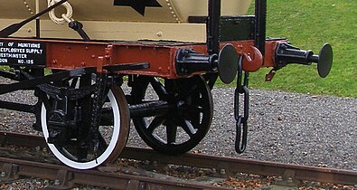 Three-link coupling on an antique tank wagon
 -
 UIC standard screw coupling, shown attached and tightened


Link and pin[edit]


.jpg)
The link-and-pin coupling was the original style of coupling used on North American railways. After most railroads converted to semi-automatic Janney couplers, the link-and-pin survived on forest railways. While simple in principle, the system suffered from a lack of standardisation regarding size and height of the links, and the size and height of the pockets.
The link-and-pin coupler consisted of a tube-like body that received an oblong link. During coupling, a rail worker had to stand between the cars as they came together and guide the link into the coupler pocket. Once the cars were joined, the employee inserted a pin into a hole a few inches from the end of the tube to hold the link in place. This procedure was exceptionally dangerous and many brakemen lost fingers or entire hands when they did not get them out of the way of the coupler pockets in time. Many more were killed as a result of being crushed between cars or dragged under cars that were coupled too quickly. Brakemen were issued with heavy clubs that could be used to hold the link in position, but many brakemen would not use the club, and risked injury.
The link-and-pin coupler proved unsatisfactory because:
- It made a loose connection between the cars, with too much slack action.
- There was no standard design, and train crews often spent hours trying to match pins and links while coupling cars.
- Crew members had to go between moving cars during coupling, and were frequently injured and sometimes killed.
- The links and pins were often pilfered due to their value as scrap metal, resulting in substantial replacement costs.
- When a car happened to be turned 180 degrees one would have to look for a link.
- Railroads progressively began to operate trains that were heavier than the link-and-pin system could cope with.
In Britain link-and-pin couplers were common on narrow gauge industrial and military railways, and eventually evolved into a form that could be reliably coupled when the train was stationary.
The Panama Canal mules, the locomotives used to guide the ships through the locks of the Panama Canal, have link and pin couplers and side buffers. This design was chosen so that these normally solo operating locomotives could be coupled to another locomotive in the event of a breakdown. On straight track, the link and pin coupler is used. Since the vertical curve between the straight track sections and the ramp between the lock chambers has a very small radius, the difference in height would be too great for a link and pin coupler, so the locomotives must be pushed through these sections uncoupled by using the side buffers. They have an extra high buffer plate to prevent the buffers from buffer-locking in tight vertical curves.
Balance lever coupling[edit]

The balance lever coupling, also central buffer coupling with two screw coupling, is a coupler commonly used on narrow gauge railroads with tight curves. By swapping the pulling and pushing devices, the standard screw coupling used on standard gauge railroads became a center buffer coupling with one screw coupling on each side of the buffer. The screw couplers are connected to a compensating lever that pivots on a vertical trunnion on the center buffer rod, allowing an even distribution of tractive forces between the two screw couplers.[3]
Albert coupler[edit]

To avoid safety issues, Karl Albert, then director at the Krefeld Tramway, developed the Albert coupler during 1921. The Albert coupler was created as a key and slot coupler with two pins. Vehicles to be coupled were pushed together, both couplings moving to the same side. One pin was inserted, then the vehicles were pulled to straighten the coupling and the other pin inserted. This operation required less exact shunting. Due to the single-piece design, only minimal slack was possible. The system became quite popular with tram systems and narrow gauge lines.
During the 1960s most cities replaced them with automatic couplers. But even in modern vehicles, Albert couplers get installed as emergency couplers for towing a faulty vehicle.
Miller hook and platform[edit]
The link and pin was replaced in North American passenger car usage during the latter part of the 19th century by the assemblage known as the Miller platform, which included a new coupler called the Miller hook.[4] The Miller platform (and hook coupler) was used for several decades before being replaced by the Janney coupler.
Norwegian[edit]

The Norwegian coupler consists of a central buffer with a movable hook that drops into a slot in the central buffer.[5] There may also be a U-shaped safety catch on the opposite buffer that is flipped over the top of the hook to secure it. The safety device may also be a chain with a ball-shaped weight at the end that is thrown over the hook to hold it in place.[5] On railways where the rolling stock always face the same direction, the mechanical hook can be on one end of the wagon only. Not all Norwegian couplers are compatible with one another as they vary in height and width, and may or may not be limited to one hook at a time. The traction force limit is typically 350 kN.[6] Sometimes the Norwegian coupler is supplemented with auxiliary chains.
The Norwegian coupler is also known as the Lloyd coupler named after its British manufacturer F.H. Lloyd & Co. Ltd near Wednesbury or as the meat chopper coupler named after the shape of the movable hook. The Norwegian coupler allows sharper curves than the buffer and chain coupler, which is an advantage on narrow gauge railways where low speeds and reduced train loads allow a simpler system. The Norwegian coupler is found only on narrow gauge railways of 1,067 mm (3 ft 6 in), 1,000 mm (3 ft 3+3⁄8 in) or less in Great Britain and its former colonies. For example, it is used on the Isle of Man Railway, the Western Australian Government Railways, in Tanzania, on the Ffestiniog Railway, on the Lynton and Barnstaple Railway, and on the Welsh Highland Railway,
Radial couplers[edit]
Two versions of radial coupler were used in South Africa. One, the Johnston coupler, commonly known as a bell link-and-pin coupler, was introduced in 1873 and is similar in operation to and compatible with link-and-pin couplers, but bell-shaped with a circular coupler face. The other, the bell-and-hook coupler, was introduced in 1902 and is similar to the Norwegian coupler, but also with a circular coupler face and with a coupler pocket which is open at the top of the coupler face to accommodate the drawhook.[7]
Johnston coupler[edit]
The Johnston coupler, commonly known as a bell link-and-pin coupler from its bell shape, was first introduced in the Cape of Good Hope in 1873, following the establishment of the Cape Government Railways (CGR) in 1872 and the decision by the Cape government to expand the railways into the interior and to convert the existing tracks from 4 ft 8+1⁄2 in (1,435 mm) standard gauge to 3 ft 6 in (1,067 mm) Cape gauge. All new Cape gauge locomotives and rolling stock acquired from 1873 were equipped with these or similar couplers, beginning with the CGR 0-4-0ST of 1873, a construction locomotive named Little Bess.[8][9][10]

The Natal Government Railways (NGR), established in the Colony of Natal in 1875, followed suit and all locomotives and rolling stock acquired by that railway were equipped with Johnston couplers, beginning with the NGR Class K 2-6-0T in 1877.[11][12]
Likewise, in 1889, when the first locomotives were obtained by the newly established Netherlands-South African Railway Company in the Zuid-Afrikaansche Republiek, they were fitted with Johnston couplers.[9][13]
Unlike the 2 ft (610 mm) narrow gauge railways of the CGR, those of the NGR also made use of Johnston couplers. The first of these narrow gauge lines came into operation in 1906, when the first NGR Class N 4-6-2T locomotives entered service on the Weenen branch out of Estcourt.[10][14]
Coupling and uncoupling were done manually, which posed a high risk of serious injury or death to crew members, who had to go between moving vehicles to guide the link into the coupler pocket during coupling. Johnston couplers gradually began to be replaced on the South African Railways from 1927, but not on narrow gauge rolling stock. All new Cape gauge locomotives and rolling stock acquired from that year were equipped with AAR knuckle couplers. Conversion of all older rolling stock was to take several years and both coupler types could still be seen on some vehicles into the late 1950s. During the transition period, knuckle couplers on many locomotives had a horizontal gap and a vertical hole in the knuckle itself to accommodate, respectively, a link and a pin, to enable it to couple to vehicles which were still equipped with the older Johnston couplers.[9][15]
Bell-and-hook coupler[edit]
The bell-and-hook coupling system was first introduced in the Cape of Good Hope in 1902, when two CGR Type A 2-6-4T locomotives were acquired as construction engines on the new 2 ft (610 mm) narrow gauge Avontuur Railway which was being constructed out of Port Elizabeth through the Langkloof. In South Africa, these couplers were used on only the narrow gauge lines in the Cape of Good Hope.[7][10][16][17]
The coupler is similar to the Norwegian coupler. It is a radial coupler with a coupler pocket which is open at the top of the coupling face. Instead of a link and pins, it makes use of a drawhook which, upon coupling, slides over the drawhook pin in the coupler of the next vehicle in the train. To prevent the drawhook of the mating coupler from accidental uncoupling, the coupler bell is equipped with a drawhook guard, commonly known as a bridle, above the coupler pocket.[7]
Usual practice was to have a drawhook fitted to only one of the mating couplers and train crews therefore carried spare drawhooks and drawhook pins on the locomotive. While automatic coupling is possible, this rarely happens and manual assistance is required during coupling. Uncoupling is done manually by lifting the drawhook by hand to release it. The coupler could be adapted to be compatible with the Johnston coupler by replacing the drawhook with a U-shaped adapter link, which was attached using the same drawhook pin.[7]
Bell-and-hook couplers began to be replaced on the Avontuur Railway upon the introduction of Class 91-000 diesel-electric locomotives on the narrow gauge system in 1973. All new narrow gauge rolling stock acquired for that line from that year were equipped with Willison couplers. Older rolling stock were not converted and an adapter was used to enable coupling between the two types. The drawhook on the bell-and-hook coupler would be replaced with the adapter, which was attached using the same drawhook pin.[7]
-
 Bell-and-hook coupler
 -
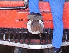 Bell-and-hook coupler with Willison adapter
 -
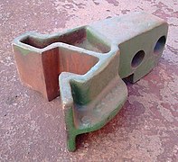 Willison coupler adapter for bell-and-hook couplers
 -
 Bell-and-hook coupler with Johnston coupler adapter link instead of a hook


Automatic couplers[edit]
There are a number of automatic train couplings, most of which are mutually incompatible. The level of automation varies and can be divided into categories:
- mechanical coupling of vehicles only, requires manual connection of pneumatic and electrical lines;
- mechanical coupling of vehicles with automatic connection of pneumatic lines, requires manual connection of electrical lines;
- mechanical coupling of vehicles with automatic connection of pneumatic and electrical lines (but not data transmission lines);
- mechanical coupling of vehicles with automatic connection of pneumatic and electrical lines (including data transmission lines);
- mechanical coupling of vehicles with automatic connection of pneumatic and electrical lines (including data transmission lines) and automatic uncoupling capability.[18]
Buckeye/Janney/MCB/ARA/AAR/APTA couplers[edit]


Lower electric connector is not typical in North America.
The Janney coupler, later the Master Car Builders Association (MCB) coupler,[19] now the Association of American Railroads (AAR) coupler, is also commonly known as a buckeye, knuckle, or Alliance coupler. The AAR/APTA TypeE, TypeF, and TypeH couplers are all compatible Janney couplers, but used for different rail cars (general freight, tank cars, rotary hoppers, passenger, etc.).
The knuckle coupler or Janney coupler was invented by Eli H. Janney, who received a patent in 1873 (U.S. patent 138,405).[20] It is also known as a buckeye coupler, notably in the United Kingdom, where some rolling stock (mostly for passenger trains) is fitted with it. Janney was a dry goods clerk and former Confederate Army officer from Alexandria, Virginia, who used his lunch hours to whittle from wood an alternative to the link and pin coupler. The term buckeye comes from the nickname of the US state of Ohio, the "Buckeye State" and the Ohio Brass Company which originally marketed the coupling.[21][22]
In 1893, satisfied that an automatic coupler could meet the demands of commercial railroad operations and, at the same time, be manipulated safely, the United States Congress passed the Safety Appliance Act. Its success in promoting switchyard safety was stunning. Between 1877 and 1887, approximately 38% of all railworker accidents involved coupling. That percentage fell as the railroads began to replace link and pin couplers with automatic couplers. By 1902, only two years after the SAA's effective date, coupling accidents constituted only 4% of all employee accidents. Coupler-related accidents dropped from nearly 11,000 in 1892 to just over 2,000 in 1902, even though the number of railroad employees steadily increased during that decade.
When the Janney coupler was chosen to be the North American standard, there were 8,000 patented alternatives to choose from. Many AAR coupler designs exist to accommodate requirements of various car designs, but all are required to have certain dimensions in common which allow for one design to couple to any other.[23]
The Janney coupler is used in the United States, Canada, Mexico, Japan, India, Taiwan, Australia, New Zealand, South Africa, Saudi Arabia, Cuba, Chile, Brazil, Portugal, China and many countries in Africa both standard gauge and narrow gauges.
The Janney coupler generally provides only mechanical coupling, only Type H adds automatic connections of pneumatic and electrical lines.[24]
Changes since 1873[edit]
Bazeley coupler[edit]
Henricot coupler[edit]
The Henricot coupler is a variation on the Janney coupler, introduced by Belgian engineer and entrepreneur Émile Henricot of Court-Saint-Étienne. It is used on certain EMUs of the National Railway Company of Belgium, including the Class 75).
- Henricot couplers
-

-
 Henricot coupler on a Belgian EMU
 -
 Closeup of Henricot coupler


Willison/SA3 coupler[edit]

An animation of the SA-3 coupler

The Willison coupler was developed in the US in 1916 to address issues present in the Janney coupling.[25]
The Russian SA3 coupler works according to the same principles as the AAR coupler but the two types are incompatible.[26] It was introduced in the Soviet Union in 1932 based on a British patent and has since been used on the whole 1,520 mm (4 ft 11+27⁄32 in) network, including Mongolia. Finnish locomotives have Unilink couplers that can couple to UIC couplers used in Finnish stock and SA3 couplers used in Russian stock.
It is also used on the 1,435 mm (4 ft 8+1⁄2 in) standard gauge networks of Iran and on Malmbanan in Sweden for ore trains. Some 2 ft (610 mm) gauge cane tramway vehicles in Queensland have been fitted with miniature Willison couplers.[27] It was introduced on the 2 ft (610 mm) narrow gauge Avontuur Railway of the South African Railways in 1973.[7]
- Russian trains are rarely longer than about 750 m (2,461 ft)[citation needed] and rarely exceed a maximum tonnage of about 6,000 t (5,900 long tons; 6,600 short tons)[citation needed]. The heaviest trains using these couplers are on Malmbanan where they are up to 9,000 t (8,900 long tons; 9,900 short tons).[28]
- Maximum force the SA3 coupler is able to carry, both tensile and compressive, is about 2.5 MN (280 STf; 250 LTf).[29]
- The maximum allowed tractive effort to the SA-3 is limited to 135 tf (1,320 kN; 133 LTf; 149 STf) (1.32 MN or 300,000 lbf) by Russian white papers.[citation needed]
- The proposed European automatic coupler is compatible with the Russian coupler but with automatic air, control and power connections.[30] Implementation is permanently delayed except for a few users. See Europe below.
- The SA3 resembles a left-handed fist.
The SA3 coupler is one of the strongest couplers in the world – maximum tonnage of a train that uses this type of coupler is about 8000 t[31] – but provides only mechanical coupling.[24] Adding automatic electrical and pneumatic connectivity is a complex challenge.[32]
There are many variations and brand names for these couplers.
As of 2020[update] CAF is working on an automatic coupler based on SA3, a possible replacement of the buffers and chain coupling on European railways.[33]
Unicoupler/Intermat[edit]

Unicoupler has been developed by Knorr from West Germany in the 1970s, in parallel with a compatible counterpart, the Intermat coupler, by VEB Waggonbau Bautzen from East Germany.[34][35] The Unicoupler/Intermat coupler can automatically couple two pneumatic lines and up to six electrical connections.[25]
This coupler is mechanically compatible with SA-3 and Willison couplers (but pneumatic and electrical connections must be done manually). The Unicoupler is also known as AK69e.
Maximum tonnage of a train that uses this type of coupler is about 6000 t.[31] AK69e and Intermat adoption failure has been attributed to economic performance.[36]
As of 2020[update] it has found limited use, it's been adopted by the Iranian Railways[37] and is also used in Germany on trains transporting iron ore between Hamburg and Salzgitter.[38]
C-AKv[edit]
The C-AKv coupler (also called Transpact) is a newer compact Willison coupler developed by Faiveley Transport.[39] It is mechanically compatible with the SA3 coupler (but pneumatic and electrical connections must be done manually), fully compatible with the Unicoupler and, if additional buffers are mounted, it can be coupled with the conventional European screw coupling as well.[40] The C-AKv coupler can automatically couple two pneumatic lines.[36] As of 2020[update] its use is limited to trains transporting ore between Rotterdam and Dillingen steelworks and lignite between Wählitz and Buna in Germany.[38]
Z-AK[edit]
The Z-AK coupler is yet another Willison coupler developed by Knorr Bremse. It was designed in response to the obvious failure of the Unicoupler/Intermat. It is compatible with the buffers and screw coupling. It is one of only few automatic couplers that cannot carry tensile forces, railway vehicles using this type of coupler must be equipped with buffers as well.[41]
Unilink coupler[edit]
The Unilink coupler is a coupler, which is used in CSI border countries such as Finland or Ukraine.[42] The coupler is compatible with both SA3 and screw coupling.[43] It is an SA3 coupler with an additional horn that allows to attach the shackle of the screw coupler and with a screw coupler that is connected to the hook of wagons equipped with screw couplers. When the screw coupler is not in use, the coupler shakle rests in a holder on the left side of the coupler. Rolling stock equipped with Unilink couplers is also equipped with side buffers, which are required when using the screw coupler.[44]
Finland uses passenger coaches equipped with screw couplers because they have the advantage over the SA3 coupler of providing a slack-free ride, as the screw couplers are always under tension and the side buffers do not separate in normal operation. Most Finish freight cars are also equipped with screw couplers. Only some heavy freight cars and Russian equipment are fitted with SA3 couplers.
Automatic Buffing Contact Coupler (ABC Coupler)[edit]
The Automatic Buffing Contact Coupler, better known as the ABC coupler, was invented by J.T. Jepson, patented in Great Britain in 1906[45] and manufactured by the A.B.C. Coupler and Engineering Company Limited in a factory in Wolverhampton.
The coupling consists of a shackle that protrudes from a central buffer and falls into a hook in the opposite buffer when coupling contact is made. The non-engaged shackle of the opposite coupler rests on the engaged shackle, securing it against disengagement by its weight. To uncouple the ABC coupling, the upper shackle that is not engaged is lifted. This causes the tail lever attached to the shackle to lift the engaged shackle clear of the hook and release the coupling.
In 1912, an improved version of the coupling with a better locking mechanism was introduced, in which a spring-loaded locking bar blocked a disk serving as the hook. This disc hook was rotated into the locked position by the approaching shackle of the opposite coupling. To release the coupling, it was sufficient to release the locking bar by pulling on a chain or a handle, which released the rotation of the disk hook.
The coupler was mainly used on narrow gauge railways of the British colonies, like e.g. the Bauchi Light Railway in Nigeria, Ceylon, Honduras or the Kalka-Shimla Railway in India.[46][47]
Stearns and Ward coupler[edit]

The Stearns and Ward coupler, known as the Ward coupler in the United Kingdom, is named after its two American inventors, Robert B. Stearns and Frank D. Ward, who were jointly granted the patent US 737673 "Car-coupling." in 1903. The coupler was specifically designed for use on elevated railways[48] as they were introduced in Chicago at the turn of the century. It was first used on the electric trains of the Northwestern Elevated Railroad in 1902. Three years later in 1905 it was introduced by Wards in the electrification of the Circle Line of the District Railway, which became the London Underground. The Ward coupler was the standard coupler on London Underground trains until 1936, when it was replaced by the Wedglock coupler, a multi-function coupler that also provided pneumatic and electrical connections.[49]
The cars must be pushed together to couple. The tongue of each coupler head enters the throat of the opposite coupler head, where the hook on the tongue turns a vertically mounted, spring-loaded coupling pin against the force of the spring. Once the hook passes the coupling pin, the spring force returns the coupling pin to its original position, holding the hook head in the coupling. When coupled, the coupler heads are free to move vertically, which should prevent a derailed car from dragging other cars with it in the event of a derailment on the elevated railway. Uncoupling is done by turning the coupling pin against the spring force with an actuating arm operated by a shunting pole or by a fixed rod with handles that can be reached from a position next to the train away from the third rail.[48]
Multi-function couplers[edit]
Multi-function couplers (MFCs), or fully automatic couplers, make all connections between the rail vehicles (mechanical, air brake, and electrical) without human intervention, in contrast to autocouplers, or semi-automatic couplers, which just handle the mechanical aspects. The majority of trains fitted with these types of couplers are multiple units, especially those used in mass transit operations.
There are a few designs of fully automatic couplers in use worldwide, including the Scharfenberg coupler, various knuckle hybrids such as the Tightlock (used in the UK), the Wedglock coupling, Dellner couplings (similar to Scharfenberg couplers in appearance), BSI coupling (Bergische Stahl Industrie, now Faiveley Transport) and the Schaku-Tomlinson Tightlock coupling.
There are a number of other automatic train couplings similar to the Scharfenberg coupler, but not necessarily compatible with it. Older US transit operators continue to use these non-Janney electro-pneumatic coupler designs and have used them for decades.
Westinghouse H2C[edit]
The Westinghouse H2C coupler, whose predecessor the H2A was first used on the BMT Standards and later the R1 through R9 classes, is currently used on the R32, R42, R62, R62A, R68, and R68A class subway cars of the New York City Subway. The A ends of the cars typically have the Westinghouse coupler and the B ends use either a semi-permanent drawbar, or a Westinghouse coupler.
WABCO N-Type[edit]

The WABCO N-Type coupler was first developed for the prototype Pittsburgh Skybus system with the initial model N-1 as applied only to the three Skybus cars. The updated model N-2 with a larger 4-inch (101.6 mm) gathering range was first applied to the new "Airporter" rapid transit cars on the Cleveland Rapid Transit line. The model N-2 used lightweight draft gear slung below the center sill, to allow for the wide swings required to go around sharp curves. This made the N-2 unsuitable for main line railroad use so an updated version N-2-A was developed for that market. The first of these were fitted in 1968 to the UAC TurboTrain with 228 electrical contacts and the Budd Metropolitan EMU with 138 contacts. Starting in the 1970s the N-2-A was fitted to the entire SEPTA Silverliner family of MU's, the NJT Arrow series of MU's and the Metro-North Railroad/Long Island Rail Road M series of MU railcars. The N-2 was also used by the PATCO Speedline, but was replaced due to issues with the electrical contacts. Later WABCO would create a new model N-3 for the BART system with a 6-by-4-inch (152.4 mm × 101.6 mm) gathering range which required a rectangular funnel.
The WABCO N-type is sometimes referred to as the pin and cup coupler or spear coupler.
Tomlinson[edit]


The Tomlinson coupler was developed by the Ohio Brass Company[21][22] for mass transit applications, but eventually found use in some mainline railroad vehicles as well. It consists of two squared metal hooks that engage with each other in a larger rectangular frame with air line connections above and below. Since the coupler's development the manufacturing arm of Ohio Brass was purchased by WABCO which now manufacturers the line along with the N-type. The Tomlinson coupler is the most widely used fully automatic heavy rail coupling in North America having been adopted by the Washington Metro, Massachusetts Bay Transportation Authority, PATCO Speedline, SEPTA Broad Street Subway, Los Angeles Metro Rail, Baltimore Metro, Miami Metro, MARTA Rail and the New York City Subway for its R44/R46 fleet and all modern classes starting with the R142. For applications outside of rapid transit the coupler had to be significantly enlarged to meet the increased strength requirements first appearing in this capacity on the Budd Metroliner and later on the Illinois Central Highliner fleet. Its relative lack of strength is one reason the N-Type has been more successful in the mainline railroad arena.
Outside the United States, the Tomlinson coupler is used on Tokyo Metro's Ginza and Marunouchi Lines[50] and on the heavy capacity Taipei Metro lines.[51]
Scharfenberg coupler[edit]


made by Dellner
The Scharfenberg coupler[52] (German: Scharfenbergkupplung or Schaku) is probably the most commonly used type of fully automatic coupling. Designed in 1903 by Karl Scharfenberg in Königsberg, Germany (today Kaliningrad, Russia), it has gradually spread from transit trains to regular passenger service trains, although outside Europe its use is generally restricted to mass transit systems. The Schaku coupler is superior in many ways to many other automatic couplers because it makes the pneumatic and electrical connections automatically and is capable of automatic uncoupling.[53] However, there is no standard for the placement of these electro-pneumatic connections. Some rail companies have them placed on the sides while others have them placed above the mechanical portion of the Schaku coupler.
Small air cylinders, acting on the rotating heads of the coupler, ensure the Schaku coupler engagement, making it unnecessary to use shock to get a good coupling. Joining portions of a passenger train can be done at very low speed (less than 2 mph or 3.2 km/h in the final approach), so that the passengers are not jostled about. Rail equipment manufacturers such as Bombardier offer the Schaku coupler as an option on their mass transit systems and their passenger cars and locomotives. In North America all the trains of the Montreal Metro are equipped with it, as are new light rail systems in Denver, Baltimore and New Jersey. It is also used on light rail vehicles in Portland, Minneapolis, the Vancouver Skytrain, and Line 3 Scarborough in Toronto. In New Zealand, it is found on the electric AM class of Auckland's suburban rail network, and on the Matangi trains of Wellington's. It also equips all the dedicated rolling stock used for the shuttle services in the Channel Tunnel.
Maximum tonnage under 1,000 t (1,100 short tons; 980 long tons).
As of 2020[update] Voith and Dellner are working on an automatic coupler based on Schaku, a possible replacement of the buffers and chain coupling on European railways.[54]
Dellner coupler[edit]

The Swedish-made Dellner coupling,[55] is a proprietary version of the Scharfenberg coupler, connecting vehicle, pneumatics and electronics at the same time. The patented energy absorption D-BOX technology allows coupling at speeds of up to 15 kilometres per hour (9 mph) with no structural damage, and up to 36 kilometres per hour (22 mph) with deformation but with the vehicles remaining on track. The patented D-REX system provides Ethernet high speed data connection at speeds of 100 Mbit/s.
Wedglock coupler[edit]

The Wedglock coupler is named for the pneumatic wedges that lock the moving parts of the coupler head in the engaged position. It is the standard automatic coupler used on London Underground trains. The coupler was introduced in 1936[56] and is manufactured by William Cook Rail.[57] and Voith.[58] The face of the coupler has a protruding, movable tongue which is inserted into the throat of the opposite coupler during coupling. Once these mechanical elements are fully engaged, their position is locked by wedges driven by a pneumatic cylinder. The pneumatic pots are located below the mechanical connection. They are simply pressed together and sealed by rubber elements. On either side of the mechanical connection are electrical contact blocks consisting of a series of butt contacts. When disconnected, the contacts are protected by the so called "Dutch oven" covers. The covers are mechanically actuated and swing open when the other coupling approaches.[56] The coupling can be engaged and disengaged from the cab using the three-position coupling switch in the cab.[59]
GF Coupler[edit]
.jpg)
.jpg)
The GF coupler, sometimes also written as +GF+ coupler, is a coupler manufacturend by Georg Fischer in Schaffhausen, Switzerland and was widely used on Swiss railways and on vehicles produced by the Swiss railway industry. It was first shown at the Swiss National Exhibition in Bern in 1914. There were three variants available, the GFN type for interurban railways, the GFT type for trams and the GFV type for mass transit.[60]
GFN and GFT[edit]
The GFN and GFT types are very similar. The only difference is that the GFT is designed for lower forces as expected in tram service. Both couplings consist of a rectangular buffer that doubles as a throat. A horizontal tongue with a hole protrudes from the inside of the throat into which the verticaly arranged locking pin hooks. To uncouple, the locking pin can be lifted with handles located behind the coupler. Optionally, the air and electrical lines can also be connected. Air connections are typically located above and/or below the mechanical coupling. The electrical contacts are located above the coupler and are protected from contamination by a hinged cover when uncoupled.
The first railways introducing the GFN type coupler where the Bern-Zollikofen-Bahn, now part of the Regionalverkehr Bern-Solothurn, the Aarau–Schöftland-Bahn, now part of the Wynental and Suhrental Railway, and the Biel–Täuffelen–Ins railway. An other important railway using the GFN type coupler is the Brünig railway. The lighter GFT type coupler was first used by the Strassenbahn Zürich–Oerlikon–Seebach[60] and was later introduced to almost all tram services in Switzerland.
GFV[edit]
The GFV differs significantly from the GFN and GFT. It is typically designed as a fully automatic multi-function coupler that can be disengaged at the push of a button in the cab. The design is more similar to a Schafrenberg coupler. The mechanical connection is made by a hemispherical element protruding from the coupling head, which is inserted and locked into a half-shell-shaped pocket on the opposite coupling head. The two air connections are located one above the other below the mechanical coupling next to the guide horn, and the electrical connections are located above the coupling as with the GFN and GFV types. The type was first introduced 1965 with the so called Gold Coast Express used as the frist mass transit trains in the Greater Zurich area. It is still widely used on Zürich S-Bahn equipment and in Belgium by the SNCB.[60]
Schwab coupler[edit]

The Schwab coupler is an automatic coupler manufactured by Schwab Verkehrstechnik AG, Schaffhausen, the legal successor to the Railway Coupler Division of Georg Fischer. The coupler automatically makes the mechanical, pneumatic and electrical connections. The mechanical locks are located on either side of the pneumatic ports. The electrical connections are located below the pneumatic ports and are protected by a cover when disconnected. Several versions are available for different applications, which can only be coupled to each other and not to other couplings, except the FK-15-10 version which can be coupled to the Scharfenberg coupling type 10. A special feature of the Schwab coupler is the inclined coupler face, which causes the coupler heads to slide past each other during coupling, so that snow and ice are scraped off the coupler faces in winter. [61]
As of 2020[update] Schwab couplers are used primarily in Switzerland in regional rail passenger transport.[62] Almost all vehicles fitted with Schwab couplers are manufactured by Stadler Rail. The best known exception are the ICN tilt trains operated by Swiss Federal Railways (SBB).
The following versions exist:
- standard gauge mainline railroads:
- FK-15-12, which are used on Stadler KISS, Stadler GTW and Stadler FLIRT
- FK-15-10, which is compatible with the Scharfenberg type 10 coupler
- metros and suburban railways: FK-9-6
- streetcars and narrow gauge railcars: FK-5.5-4 and FK-3-2.5
As of 2020[update] Wabtec is working on an Digital automatic coupling (DAC) based the Schwab coupler, a possible replacement of the screw couplers in the European rail freight service.[33] The coupler is able to handle tensile forces up to 1500 kN and compressive forces up to 2000 kN and is therefore one of the strongest couplers ever designed for European railways.[61]
Shibata coupler[edit]
The Shibata coupler is a variation of the Scharfenberg coupler which was developed by Japanese Government Railways (JGR) engineer Mamoru Shibata in the 1930s for electric trains.[b] It is the standard coupler type for all passenger trains in Japan as well as on commuter and subway trains in South Korea.
Shinkansen (bullet train) rolling stock utilize a variation of the Shibata coupler developed by Sumitomo Metal Industries in the 1960s which uses rotary tight-lock pins, and which coincidentally bears a closer resemblance to the Scharfenberg coupler rather than the Shibata coupler.[63]
- Shibata couplers
-
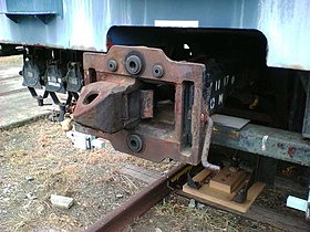 Shibata close contact ("Mitchaku") coupler
 -
 Shibata rotary coupler on E4 Series Shinkansen


Dual couplings and match wagons[edit]

Sometimes a wagon with one coupling system needs to be coupled to wagons with another coupling type This may be needed when taking metro rolling stock from its manufacturer to the city where it is to be used. There are two solutions:
- use a barrier vehicle(s) which has different couplings at either end.
- use a coupling adaptor.
- use a match wagon which has the same dual coupling at both ends.
Only some kinds of couplings coexist on the end of a wagon at the same time, because amongst other reasons they need to be at the same height. For example, in the Australian state of Victoria, engines had the AAR coupler, with buffers, and the chain mounted on a lug cast into the AAR coupler.
A barrier vehicle / wagon in Britain and "transition car" in North America) has different kinds of couplings at each end. If a pair of barrier vehicles is used, a rake of wagons using coupling A can be inserted into a train otherwise using coupling B.
A coupling adaptor or compromise coupler might couple to an AAR coupling on a wagon, and present, for example, a meatchopper coupler or rapid transit coupler to the next wagon. Such an adaptor might weigh 100 kg (220 lb). An adapter piece allows a Janney coupler mate with an SA3 coupler.[64]
Dual coupling[edit]
Sets of carriages[edit]
Automatic couplers like the Janney are safer in a collision because they help prevent the carriages telescoping. British Rail therefore decided to adopt a Janney variant for its passenger carriages, with the coupler able to swing out of the way for coupling to engines with the traditional buffer and chain system.
In New South Wales, sets of carriages were permanently coupled with a fixed bar, since the carriages were disconnected only at the workshops. Freight cars are sometimes coupled in pairs or triplets, using bar couplings in between.
Articulated sets of carriages or wagons share the intermediate bogies, and have no need for couplings in the intermediate positions.
Brake couplings[edit]
Couplings are needed for any continuous braking systems.
Electronically controlled brakes[edit]
Electronically controlled pneumatic brakes (ECP) need a method of connecting electrically adjacent wagons, both for power and for command signals, and this can be done by plugs and sockets, or by very short range radio signals.
Draw gear[edit]
A draw gear (also known as a draft gear) is the assembly behind the coupling at each end of the wagon to take care of the compression and tension forces between the wagons of trains. Early draw gears were made of wood, which was gradually replaced by steel.
Janney couplers have the draft gear in a centersill to absorb the pushing and pulling forces (slack action).[65]
There is also a draw gear behind tightlock couplers, SA3 couplers, C-AKv couplers, Scharfenberg couplers, and other multi-function couplers.
In the case of buffers and chain couplers, the draw gear behind the hooks, if any, will absorb the tension, while the side buffers will absorb the compression.
Some couplers may not have a draw gear.
Model railway couplers[edit]
On model railroads couplers vary according to scale, and have evolved over many years. Early model trains were coupled using various hook-and-loop arrangements, which were frequently asymmetrical, requiring all cars to be pointing in the same direction. In the larger scales, working scale or near-scale models of Janney couplers were quite common, but proved impractical in HO and smaller scales.
For many years, the "X2F" or "Horn-Hook" coupler was quite common in HO scale, as it could be produced as a single piece of moulded plastic. Similarly, for many years, a "lift-hook" coupler known as the Rapido and developed by Arnold, a German manufacturer of N-scale model trains, was commonly used in that scale.
The chief competitor of both these couplers, more popular among serious modellers, was the Magne-Matic, a magnetically released knuckle coupler developed by Keith and Dale Edwards, and manufactured by Kadee, a company they started. While they closely resemble miniature Janney couplers, they are somewhat different mechanically, with the knuckle pivoting from the center of the coupler head, rather than from the side. A steel pin, designed to resemble an air brake hose, allows the couplers to be released magnetically; the design of the coupler head prevents this from happening unless the train is stopped or reversed with a mated pair of couplers directly over an uncoupling magnet. An earlier, mechanically tripped version of the design had a straight pin extending down from the knuckle itself, which engaged a diamond-shaped mechanical "ramp" between the rails, which had to be raised above rail height when uncoupling was desired.
Once the Kadee patents ran out, a number of other manufacturers began to manufacture similar (and compatible) magnetic knuckle couplers.
An exact-scale HO model of the AAR coupler has been designed and manufactured by Frank Sergent.[66] This design uses a tiny stainless steel ball to lock the knuckle closed. Uncoupling is achieved by holding a magnetic wand over the coupler pair to draw the balls out of the locking pockets.
In O scale, an exact-scale working miniature version of the "Alliance" coupler was manufactured from the 1980s by GAGO models in Australia. Since 2002 it has been marketed by the Waratah Model Railway Company.[67] European modellers tend to use scale hook and chain couplings.
In British 00 scale (similar to H0 scale) models the 'tension lock' coupler developed by Tri-ang is standard. This is similar in operation to the meatchopper type of coupling. Remote uncoupling is possible by using a sprung ramp between the rails. The design of the hooks is such that the couplings will not uncouple when under tension (instead depressing the ramp). When the train is pushed over the ramp, it will lift the coupling hooks as the train passes over. By halting the train over the ramp, it is split at this point. While it works well, it is often seen as ugly and obtrusive[citation needed] (although smaller designs are available, these are not always fully compatible with other models) and many[citation needed] British modellers prefer to retrofit either Kadee types or working hook and chain couplings.
A recent development is an interchangeable coupling which plugs into a standardised socket, known as NEM 362 and which can be easily unplugged as required. This allows the modeller to easily standardise on whatever coupling is desired, without individual manufacturers needing to change their coupling type.
In 7 mm scale, scale working Norwegian couplings are now being manufactured by Zamzoodled[68] in the UK.
A comparison of coupler types was published in "An introduction to Couplers".[69]
Wooden and plastic trains[edit]
Toy trains have a wide variety of incompatible couplers.
Accidents[edit]
Different kinds of coupling have different accident rates.
- The Murulla rail accident of 1926 involved the breakage of a "drawhook" leading to a downhill runaway and then a collision. Drawhooks imply "buffers and chain couplers".[70]
- Round Oak rail accident – 1858 – coupling broke and the rear of train rolled back.
See also[edit]
- Buckeye Steel Castings
- Drawbar
- Gangway connection
- Gender of connectors and fasteners
- Jane's World Railways, lists the coupler(s) used on any railway system
- Railway coupling by country
- Railway coupling conversion
- Slack action
- Three-point hitch
Notes[edit]
References[edit]
- ^ Train Couplers 101 - How do train cars stay together?, retrieved 2023-04-17
- ^ DAC Report 2020, p. 7.
- ^ Bruno Lämmli: Zug- / Stossvorrichtung. Auf: Lokifahrer, 2021.
- ^ Miller Hook
- ^ a b "Setesdals Railway". Members.ozemail.com.au. Archived from the original on 2016-03-04. Retrieved 2016-04-08.
- ^ "Lloyd MCA-PH". LAF.
- ^ a b c d e f Suid-Afrikaanse Vervoerdienste (South African Transport Services) (1983). Passassierswa- en Trokhandboek (Passenger Carriage and Truck Manual), Vol 1, Hoofstukke 1-15 (Chapters 1-15). South African Transport Services, 1983. Chapter 13.
- ^ George Hart, ed. (1978). The South African Railways - Historical Survey. Bill Hart, Sponsored by Dorbyl Ltd. pp. 9, 11–13.
- ^ a b c Holland, D. F. (1972). Steam Locomotives of the South African Railways. Vol. 2: 1910-1955 (1st ed.). Newton Abbott, England: David & Charles. pp. 51–52, 117–118. ISBN 978-0-7153-5427-8.
- ^ a b c Paxton, Leith; Bourne, David (1985). Locomotives of the South African Railways (1st ed.). Cape Town: Struik. pp. 6, 110–112, 156–157. ISBN 0869772112.
- ^ Holland, D.F. (1971). Steam Locomotives of the South African Railways. Vol. 1: 1859–1910 (1st ed.). Newton Abbott, England: David & Charles. pp. 84–87, 109–112. ISBN 978-0-7153-5382-0.
- ^ Espitalier, T.J.; Day, W.A.J. (1944). The Locomotive in South Africa - A Brief History of Railway Development. Chapter III - Natal Government Railways. South African Railways and Harbours Magazine, May 1944. pp. 337-340.
- ^ Espitalier, T.J.; Day, W.A.J. (1944). The Locomotive in South Africa - A Brief History of Railway Development. Chapter IV - The N.Z.A.S.M.. South African Railways and Harbours Magazine, October 1944. pp. 762, 764.
- ^ Espitalier, T.J.; Day, W.A.J. (1944). The Locomotive in South Africa - A Brief History of Railway Development. Chapter III - Natal Government Railways (Continued). South African Railways and Harbours Magazine, September 1944. p. 669.
- ^ South African Railways & Harbours/Suid Afrikaanse Spoorweë en Hawens (15 Aug 1941). Locomotive Diagram Book/Lokomotiefdiagramboek, 2′0″ & 3′6″ Gauge/Spoorwydte, Steam Locomotives/Stoomlokomotiewe. SAR/SAS Mechanical Department/Werktuigkundige Dept. Drawing Office/Tekenkantoor, Pretoria. pp. 6a-7a, 25.
- ^ Espitalier, T.J.; Day, W.A.J. (1944). The Locomotive in South Africa - A Brief History of Railway Development. Chapter II - The Cape Government Railways (Continued). South African Railways and Harbours Magazine, April 1944. pp. 253-257.
- ^ Dulez, Jean A. (2012). Railways of Southern Africa 150 Years (Commemorating One Hundred and Fifty Years of Railways on the Sub-Continent – Complete Motive Power Classifications and Famous Trains – 1860–2011) (1st ed.). Garden View, Johannesburg, South Africa: Vidrail Productions. p. 232. ISBN 9 780620 512282.
- ^ DAC Report 2020, p. 13.
- ^ "Internet Archive Search: creator:"Master Car-Builders' Association"". Archive.org. Retrieved 2016-04-08.
- ^ "Eli Janney - The Janney Coupler". Inventors.about.com. Archived from the original on 2008-11-06. Retrieved 2016-04-08.
- ^ a b "Ohio Brass Co. Company Profile on". Aecinfo.com. Retrieved 2016-04-08.
- ^ a b "Ohio Brass Started As Small Jobbing Foundry In 1888" (PDF). Rootsweb.ancestry.com. Retrieved 2016-04-08.
- ^ AAR Manual of Standards and Recommended Practices, Section S, Part III:Coupler and Yoke Details, Issue 06/2007
- ^ a b DAC Report 2020, p. 30–31.
- ^ a b DAC Report 2020, p. 19.
- ^ "ДЖД - Толковый словарь". Railways.id.ru. 2005-05-16. Archived from the original on 2014-04-26. Retrieved 2016-04-08.
- ^ Light Railways, October 2013, p. 23
- ^ "Sweden introduces 32.5-tonne axleloads on Iron Ore Line". Archived from the original on 2017-10-29. Retrieved 2017-10-29.
- ^ DAC Report 2020, p. 22.
- ^ "The SAB WABCO C-AK for goods wagons". Archived from the original on May 19, 2009. Retrieved October 15, 2009.
- ^ a b State of the Art on Automatic Couplers 2017, p. 18.
- ^ DAC Report 2020, p. 20.
- ^ a b DAC Report 2020, p. 5.
- ^ "The Automatic Center Coupler for European Railways". Archived from the original on July 18, 2011. Retrieved November 16, 2010.
- ^ "History of the European Automatic Centre Coupler for Goods Wagons". Archived from the original on October 30, 2007. Retrieved August 3, 2008.
- ^ a b State of the Art on Automatic Couplers 2017, p. 19.
- ^ DAC Report 2020, p. 9.
- ^ a b DAC Report 2020, p. 11.
- ^ "Faiveley Transport Group - Systems and services for the railway industry". Faiveleytransport.com. Retrieved 2016-04-08.
- ^ State of the Art on Automatic Couplers 2017, p. 26.
- ^ State of the Art on Automatic Couplers 2017, pp. 19–20.
- ^ Analysis of the basic parameters for maintaining the technical and operational compatibility of the 1520 mm and 1435 mm gauge rail systems at the Commonwealth of Independent States (CIS)/European Union (EU) border. Rolling stock. Passenger carrriages (PDF). OSJD-ERA Contact Group. 2013. Retrieved 2023-12-16.
- ^ "All purpose couplers: "Willison" type couplers". LAF. Archived from the original on 2021-05-07. Retrieved 2021-02-17.
- ^ DAC Report 2020, p. 10.
- ^ GB patent 190525511A, J.T. Jepson, "Improvements in connection with Automatic Couplings for Railway Vehicles and the like", published 1906-08-16
- ^ "ABC Couplers". Archived from the original on May 21, 2009. Retrieved October 4, 2008.[dead link]
- ^ ABC
- ^ a b US patent 737673, Robert B. Stearns & Frank D. Ward, "Car-coupling", published 1903-09-01
- ^ "Coupling, Handing and UNDMs". Trainweb.org. 2002-08-24. Retrieved 2016-04-08.
- ^ "Prototype Couplers". Sumida Crossing.
- ^ OTIS Wang. "臺北捷運C381型高運量電聯車". 雪花台灣.
- ^ "Voith". Voithturbo.de. Retrieved 2016-04-08.
- ^ DAC Report 2020, pp. 26, 30–31.
- ^ DAC Report 2020, pp. 5, 23.
- ^ "Dellner Couplers - Automatic and Semi-Permanent Couplers". Railway Technology. Retrieved 2016-04-08.
- ^ a b "Coupling, Handing and UNDMs". Tubeprune.
- ^ "Coupler systems for trains and metros". William Cook.
- ^ "Voith at Railtex 2013 More Sustainable Vehicle Components for Rail Transport". Voith.
- ^ "Coupling & uncoupling".
- ^ a b c Madörin, Dominik. "+GF+-Kupplung". tram-bus-basel.ch. Retrieved 2023-12-21.
- ^ a b DAC Report 2020, p. 29.
- ^ DAC Report 2020, p. 26.
- ^ "Prototype Couplers". Sumida Crossing. Retrieved 2016-04-08.
- ^ Adapter piece
- ^ How Does a Draft Gear Absorb Railcar Energy?. YouTube. 8 March 2012. Retrieved 2016-04-08.[dead YouTube link]
- ^ "Sergent Engineering Home Page". Sergentengineering.com. Retrieved 2016-04-08.
- ^ "ModelOKits – Product Information and Online Store". Waratahmrc.com.au. Archived from the original on 2014-05-17. Retrieved 2016-04-08.
- ^ "Zamzoodled home page". Zamzoodled.co.uk. Retrieved 2016-04-08.
- ^ Model Railways in Australia, issue 3, 2009.
- ^ "MURULLA ACCIDENT". The Sydney Morning Herald. National Library of Australia. 23 October 1926. p. 16. Retrieved 17 December 2011.
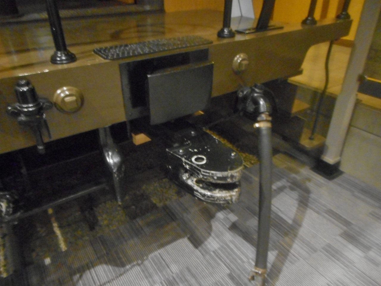
Sources[edit]
- Tymczasowe wytyczne obsługi sprzęgu samoczynnego typu UIC/OSŻD, radzieckiego – typu SA3 oraz sprzęgu mieszanego [Interim guidelines for operation of automatic coupler type UIC/OSJD, Soviet—SA3 and adapter] (in Polish). Warsaw: Ministerstwo Komunikacji. 1979.
- Development of Functional Requirements for Sustainable and Attractive European Rail Freight: D5.1 – State of the Art on Automatic Couplers (PDF) (Technical report). Shift2Rail. 3 March 2017.
- Prof. Dr. Markus Hecht, Markus; Mirko Leiste, M.Sc.; Saskia Discher, B.Sc., eds. (29 June 2020). Development of a concept for the EU-wide migration to a digital automatic coupling system (DAC) for rail freight transportation (PDF) (Technical report). Berlin: Berlin University of Technology for the Federal Ministry of Transport and Digital Infrastructure (BMVI).
- Norfolk & Western Railway Co. v. Hiles (95-6), 516 U.S. 400 (1996) (U.S. Supreme Court decision by Justice Clarence Thomas)
- Eli Janney — The Janney Coupler Archived 2008-11-06 at the Library of Congress Web Archives (based on above case)
- Dellner Couplers AB — Automatic and Semi-Permanent Couplers
- Vancouver SkyTrain Light Rail Network, Canada (these two for Dellner data)
- JANE'S WORLD RAILWAYS
- How couplings work
- White, John H. (1985) [1978]. The American Railroad Passenger Car. Baltimore, Maryland: Johns Hopkins University Press. ISBN 978-0-8018-2743-3.
Further reading[edit]
Tomlinson, G. W. (1991). "Electrical Systems via Couplers". Proceedings of the Institution of Mechanical Engineers, Part F: Journal of Rail and Rapid Transit. 205 (1): 65–78. doi:10.1243/PIME_PROC_1991_205_217_02. S2CID 111315979.
External links[edit]
- US patent 4102459, Axel Schelle & Kuno Nell, "Adaptor device for coupling railway vehicles having different types of couplers", published 1978-07-25, Adapter between Janney coupler and SA3 coupler