Diesel injection system
A diesel injection system is a subsystem in diesel engines . The purpose is to create a flammable mixture that is as homogeneous as possible. For this purpose, the diesel fuel , which is under overpressure , is mixed via a pipeline with the aid of a controlled valve and an atomizing nozzle with oxidizing gas, usually air , which is strongly heated by compression . The pressure is increased with the help of an injection pump .
history
From the very beginning, when developing the compression-ignition engine , Rudolf Diesel sought direct injection of the fuel into the combustion chamber, but failed because of the inadequacy of the pumps available and the lack of precision of the injection valves. As a compromise, the detour via blowing in the fuel with compressed air was chosen. This enabled the liquid fuel to be dosed with sufficient accuracy and finely distributed in the combustion chamber.
On March 14, 1909, Prosper L'Orange received a patent DRP 230 517 on the pre-chamber injection with needle injection nozzle and a controllable injection pump . As a result, the heavy and fragile air compressor was no longer required and the diesel engine was no longer only used stationary or in ships.
At the beginning of the 20th century, fuel injection with compressed air, which had been common up until then, was replaced by injection systems with an antechamber within a few years.
A development in the 1930s by the Detroit Diesel Company, DDC, was the English called Unit Injector System ( UIS ). It was first used in the late 1930s in relatively slow-speed marine, railroad, and truck diesel engines. An essential characteristic is the provision of an injection pump for each cylinder with very short pressure lines to the injection nozzle . The pumps were mechanically driven by push rods. The pump-nozzle system developed in the 1990s is based on this system.
Prior to 1987, diesel engines with direct injection were used exclusively in commercial vehicles and large engines. Because of the initially loud and harsh engine noise, this type of engine was not used in passenger cars, as the comfort requirements were seen as more important than the lower specific consumption. Advances in injection technology improved the noise level, so that the direct injection process without an antechamber together with an exhaust gas turbocharger prevailed in the 1990s.
The direct injection diesel engine was first in passenger car mass production from 1987 in the of Fiat offered Fiat Croma id TD used. The engine was developed in a Fiat research center in Naples. For this purpose, an engine known from the commercial vehicle sector was equipped with an electronic injection control, which improved the running smoothness to a level usable for passenger car conditions. The engines of this type developed a high torque even at low speeds and thus enabled both good driving performance and low consumption.
Mixture formation
Historically, various methods of mixture formation were used. Many reflect the state of the art at the time.
Combustion chamber design
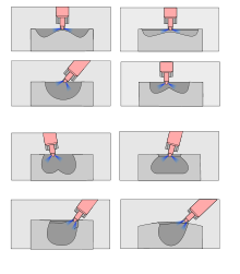
Basically, the injection processes can be divided into a compact combustion chamber and a subdivided combustion chamber:
- Split combustion chamber in chamber engines, which, depending on their subdivision, are assigned to the prechamber , vortex chamber and Lanova injection processes
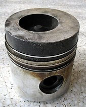
- One-piece combustion chamber without an antechamber in the case of direct injection , whereby the combustion chamber , which is expediently adapted depending on the method , can be partially or entirely in the piston crown .
Components
Fuel filter
→ Main article: fuel filters
In diesel injection systems, fuel filters with a significantly larger volume are provided than in gasoline engines, for example. The purpose is to hold back the finest dirt particles, which would otherwise wear out the finely machined, high-precision injection pumps and the injection injectors prematurely and thus render them unusable.
The significantly larger filter surface allows fine-meshed filters that are slowly flowed through. This allows high separation rates to be achieved.
In addition, the vertically installed filter housings are used to separate specifically heavier water that was brought in through condensation of air humidity or poor fuel quality. This water collects in the filter base. As part of regular maintenance, any water that may be present can be drained off using an appropriate device.
pump
→ Main article: Injection pump
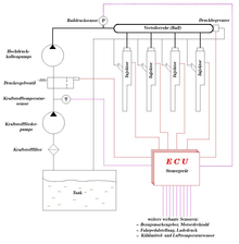
As a unit, the pump has several tasks. On the one hand, it serves the purpose of transporting fuel from the fuel tank to the engine. For this purpose, it has a fuel pump , which usually runs at the same speed as the internal combustion engine. In the case of fuel pumps without volume regulation, the amount of fuel delivered follows the engine speed. Since the amount delivered is higher than the actual requirement, the excess is returned to the fuel tank via a separate return line. In this way, excessive, local heating in parts of the injection pump as a result of the inevitable friction can be reduced.
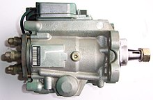
In addition, the pump has at least one further high-pressure pump that determines both the time and the amount of the actual fuel injection.
Various pump systems are used to build up the injection pressures in the above processes:
- for engines with prechamber or vortex chamber injection
- Single injection pump
- Distributor injection pump or
- In-line injection pump
- for engines with direct injection
- Single injection pump
- In-line injection pump
- Distributor injection pump
- Pump-nozzle injection systems or
- Common rail injection
Atomizing nozzle and valve unit (injector)
→ Main article: Injection nozzle (diesel engine)
The so-called injector is a combination of an atomizing nozzle and a valve and is built into the cylinder head .
In purely mechanical systems, the nozzle needle is pressed into the seat by one or more compression springs of the nozzle holder. This sub-unit is designed as an atomizing nozzle and protrudes into the combustion chamber of the diesel engine. The injection pump generates a pulse-shaped pressure surge in the line to the valve-nozzle unit. This causes a force acting against the spring force via a piston, which lifts the sealing needle out of its seat. The diesel fuel , which is still under pressure, is atomized through the nozzle and injected into the air in the combustion chamber, which is strongly heated by compression, and the fuel starts to burn immediately. If the fuel pressure drops, the nozzle needle is pushed back into its seat by the spring force and the atomizer nozzle is closed.
The nozzle opening pressure depends on the technology and is between 115 and 300 bar . The maximum injection pressure can be over 2000 bar.
In modern injectors of the Common Rail system , the nozzle needles are actuated by an electrical signal either electromagnetically or piezoelectrically via a servo valve . As a result, the nozzles only open at high (more than 1800 bar) and low pressure (250 bar) when the injector is activated, and thus independently of the constant fuel pressure .
control
In the early days, the injection quantity was controlled purely mechanically, similar to that of a steam engine, with the help of centrifugal governors and pressure-controlled by means of hydraulic throttles via the fuel delivery pump following the engine speed. These auxiliary variables, together with the foot regulation of the injection quantity ( foot pedal ), acted on the quantity regulation of the high pressure pump.
In the course of reducing exhaust gas pollutants and for reasons of comfort (noise generation), the relatively sluggish, mechanical controls could not be further developed. Since the 1990s, this task has been performed by an electronic engine control . Strictly speaking, it is mostly not an open control , but a closed control . The actual state measured by a sensor is compared with a calculated target state ( feedback ) and the deviation in the closed control loop is then minimized via an actuator . The engine control software used for this is often referred to as electronic engine management .
Jump start
- → Main article: glow plug
Web links
Individual evidence
- ↑ http://www.hueber.de/sixcms/media.php/36/Diesel.pdf Diesel: "It's nice to invent like that."


