
Francis turbine


The Francis turbine is a very universally applicable water turbine named after the engineer James B. Francis from the USA , in which the impeller is flown radially from the outside.
history
The Francis turbine is a further development of the Fourneyron turbine . This turbine had the disadvantage that the water was swirled during the transition from the tail unit located inside the impeller to the rotor, so that optimal efficiency could not be achieved. A first suggestion for building a turbine with a flow in the opposite direction, i.e. from outside to inside, came from Jean-Victor Poncelet in 1826. He had previously improved the undershot waterwheel by providing it with curved blades. Poncelet suggested putting his waterwheel on one side so that the water could exit evenly through the center of the wheel, rather than having to change direction of flow to exit the shovel. In 1838 the American Samuel B. Howd received a patent for an "improved water wheel" which was arranged lying down in a shaft and flowed through from the outside to the inside. Around 1849 James B. Francis improved the design of Howd and developed the technology further by conducting precise tests on the turbine, publishing the results and formulating rules for the design of the impeller.
Working principle


Today Francis turbines are mostly designed as spiral turbines . The inflowing water is distributed over a helical housing , the spiral , in additional swirl and evenly around the circumference of the turbine before it enters the guide vane ring. Turbines without this volute casing are called shaft turbines . They are less efficient than spiral turbines and are now only used in small hydropower plants with low head.
In Francis turbines, the water enters the impeller tangentially and leaves it axially. A guide vane ring with adjustable guide vanes regulates the flow of water onto the oppositely curved vanes of the impeller, which deflects it in the direction of the rotor axis. After flowing through the impeller, the water is diverted through a suction pipe acting as a diffuser in extension of the turbine axis.
The guide vanes at the inlet act as an actuator ; the joint setting of their angle means that the speed and thus the output of the turbine is kept constant when the load of the connected generator changes and when the water level changes. The Francis turbine is a positive pressure turbine; the pressure at the impeller inlet is higher than at the impeller outlet.
The controller belonging to the turbine records the speed of the turbine on the shaft as a controlled variable and converts the result in a servo-hydraulic way into a manipulated variable that opens or closes the guide vanes according to the speed deviation. The design effort for regulating the turbine is considerable and makes up a noticeable part of the investment in a Francis turbine.
The efficiency of the Francis turbine varies depending on the design and operating point. Modern Francis turbines achieve efficiencies of over 90%. Francis turbines can also be designed as pump turbines , such as the Isogyre pump turbine .
Application area

The Francis turbine is the most common type of turbine in hydropower plants . It is used for medium heads and medium flow rates. It is therefore used in run-of-river power plants and storage power plants. Their power spectrum ranges from 10 kW to over 700 MW .
The record for the head of Francis turbines is 695 m at the Häusling pumped storage power plant in the Zillertal, with two units of 180 MW each.
The application area of the Francis turbine overlaps with that of the Pelton turbine and the Kaplan turbine . Compared to Pelton turbines, a Francis turbine can process higher flow rates with smaller dimensions. Because the Francis turbine can only be controlled via the guide vane ring and the blades of the rotor are fixed in contrast to those of a Kaplan turbine, the head must be kept relatively constant, so that in low-pressure power plants on rivers with head heights fluctuating after discharge, Kaplan Turbines are used.
Picture gallery
- Francis turbines

Opened Francis turbine. The impeller (brown) is mounted on the shaft (black)
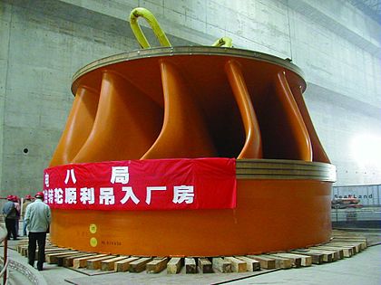
Impeller for the power plant at the
Three Gorges Dam
Impeller from 1930 for the Chippawa power station on Niagara Falls

Parts of the Francis turbine


Special designs
Flap impeller turbine

The flap impeller turbine can be viewed as a special form of the Francis turbine. In this turbine, the impeller has adjustable blades, while the stator is not adjustable. The impeller has a similar shape to the stator of the Francis turbine. The efficiency is similar to that of the Francis turbine at full load, but does not decrease as sharply with increasingly closed flaps as with a Francis turbine with a closed guide vane ring. Water quantities from approx. 15% opening of the flaps can be used economically. The flap impeller turbine is only used in small hydropower plants up to 500 kW when strongly fluctuating amounts of water have to be processed and only one turbine is to be used.
Web links
literature
- Robert Honold, Karl Albrecht: Francis turbines . A textbook for school and practice; Theory of water turbines with special consideration of the Francis turbine. R. Schulze Verlag, Mittweida 1908, ISBN 0-484-95815-1 (reprint 2018 FB&C, Classic Reprint).
Individual evidence
- ↑ a b How water turbines work. (PDF) (No longer available online.) In: alt.fh-aachen.de. P. 1 , archived from the original on October 10, 2016 ; accessed on October 10, 2016 .
- ↑ a b Information on Turbines. In: Seneca Creek Greenway Trail. February 3, 2009 (English).
- ↑ Patent US861 : Improved water-wheel. Published July 28, 1838 , Applicant: Samuel B. Howd.
- ↑ a b Turbine forms: Francis, Kaplan and Pelton turbines. In: diebrennstoffzelle.de. Retrieved October 10, 2016 .
- ↑ Practical course on Francis turbine test stand. (PDF) In: htw-dresden.de. P. 2 , accessed October 10, 2016 .
- ↑ Jürgen Giesecke, Emill Mosonyi: Hydropower plants planning, construction and operation . Second, revised edition. Springer, Berlin, Heidelberg 1998, ISBN 3-662-10859-3 , 15.2 Francis turbines, p. 435 .