Pelton turbine


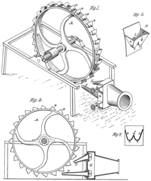
The Pelton turbine is a free jet turbine (“partially pressurized constant pressure turbine ”) for hydropower plants . It was designed in 1879 by the American engineer Lester Pelton and patented in 1880.
A Pelton turbine uses the kinetic energy of the water. This form of energy is created by converting the potential energy of the water, which comes from a higher water body, e.g. B. a reservoir that flows towards the machine. Pelton turbines are mainly used in hydropower plants with a high usable gradient, but rather lower flow rates ( high pressure power plants ).
history
Lester Pelton based the construction of his turbine on the reaction principle rediscovered by the German doctor and physicist Johann Andreas von Segner , who based on it, built the first reaction water wheel in 1750 . Before this time, the principle of the free jet turbine was implemented in horizontal wheel water mills made of wood, but with low efficiency.
Pelton's turbine modified a turbine developed by Samuel Knight and achieved a higher degree of efficiency compared to this. This led to the Pelton turbine becoming the industry standard.
functionality
Working principle
In the Pelton turbine, the headwater flows in a jet at very high speed from one or more nozzles arranged tangentially to the circumference of the impeller onto the blades of the impeller. Each of the up to 40 blades is divided by a sharp edge, the so-called central cutting edge , into two approximately hemispherical half- blades , so-called cups. The water jet from the nozzles hits the center of the cutting edge tangentially. The function of the cups is to divert the water in the opposite direction so that the kinetic energy can be transferred to the impeller according to the principle of actio and reaction . This was Pelton's innovation.
The circumferential speed of the blade circle should be exactly half the speed of the water jet. Since the water in the blades is deflected by almost 180 degrees, it then gives off almost all of its energy to the blades (when viewed without friction). The diameter of the turbine depends on the generator speed and the available water pressure or the speed of the water jet.
Arrangement in the power house
The Pelton turbine is set up in the power house in such a way that the lower edge of the impeller is definitely above the highest underwater level in order to prevent the rotating wheel from submerging. The housing, which is open at the bottom, is set up above a shaft through which the used motive water reaches the underwater without pressure. The housing and the drainage shaft are ventilated with ambient air. A suction pipe from the turbine into the underwater, as is usual with reaction turbines, cannot be used with the Pelton turbine; the difference in height between the nozzle outlet and the underwater level can therefore not be used.
Nozzles
In the nozzle, the static pressure of the headwater is converted into jet speed. A nozzle needle, a conical-teardrop-shaped regulating body with a flow around it, is provided as an actuator in each nozzle, which can be moved in the longitudinal direction by a control rod to adjust the flow cross-section. By means of the adjustment of the nozzle needle is controlled by the turbine controller , the rotational speed of the turbine controlled, as it serves as a shut-off device for starting or shutting down the turbine.
In order to reduce the pressure surge in the penstock in the event of an emergency shutdown (the immediately necessary shutdown of the turbine in order to prevent it from being destroyed by overspeed, usually caused by a load shedding ) , jet deflectors are usually installed. These are pivotable baffles in front of the nozzle mouths, which in the event of a rapid shutdown immediately divert the water jet or jets away from the impeller blades into the housing in order to prevent the power output. Only then are the nozzle needles and the gate valves or ball valves of the pressure pipeline slowly closed.
The number of nozzles depends on the throughput, whereby one nozzle can process a maximum of approx. 10 m³ / s. If the absorption capacity is to be higher, the number of nozzles must be increased, but with a horizontal shaft position only two nozzles are technically sensible because with a higher number of nozzles, the driving water that is already in use as spray falls back onto the impeller and slows it down again, as does the jet jets would disturb. If an even higher throughput is required, another impeller is arranged on the same shaft - but usually in a separate housing - or a turbine with a vertical shaft is built. In this case four nozzles are normally used, but Pelton turbines with six nozzles have already been delivered (from Escher Wyss, Ravensburg).
Equal pressure principle
In the pressure line in the inflow to the nozzle there is - depending on the height of fall - a high pressure (up to 200 bar ), between the nozzle outlet and the impact on the blading there is normal atmospheric pressure in the jet itself. Hence the classification as a constant pressure turbine, the water has the same (ambient) pressure before the power output at the turbine wheel and afterwards. The Pelton turbine is called partially pressurized because only some of the shovel buckets are pressurized by the jet at the same time, while, for example, with fully pressurized Kaplan and Francis turbines, the entire circumference of the impellers is flowed through by the head water.
Impeller and blades
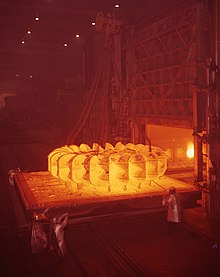
The blades on the impeller side, which do not contribute to power generation during rotation, move through air or spray. This medium has a significantly lower density and so the ventilation losses of the Pelton turbine remain comparatively low. Since each blade only briefly transfers force to the wheel when passing the nozzle (s) and then remains powerless again and is also exposed to strong centrifugal forces, the risk of fatigue fracture is very high due to the alternating stress in the root area of the cup , which must therefore be dimensioned accordingly become.
There are different manufacturing processes to meet the high requirements:
- Initially, cast blades were individually bolted to a wheel.
- As a part forged and then milled impellers, which represent the best quality but also quite expensive solution.
- The wheel can be cast in one piece, there is a risk of undetected casting defects that can later lead to the breakage of the wheel or a large part of the power plant.
- The variant forged root wheel with welded on cups.
- The patented “MicroGussTM process”, whereby the individual cups are built up on the forged root wheel in a kind of build-up welding process.
The middle cutting edge is almost razor-sharp when it is used for the first time. The cups would be destroyed by the forces of water that occur if no central cutting edge were used to divide and direct the jet. At a fall height of 1000 meters, the water jet can reach a speed of almost 500 km / h. The highest realized impact speed is approx. 185 m / s (666 km / h); With this value it is understandable that the central cutting edge is indispensable in every shovel. There is also the option of protecting the cups from excessive erosion wear , especially from foreign bodies in the water in the form of small stones or sediments , by applying a protective layer in the HVOF process.
In order for a jet to strike a blade at any time, a wheel geometrically requires at least 14 blades (pairs of cups). In practice, Pelton wheels are built with 20 to 40 blades. A jet typically sweeps two blades at a time.
Dimensions
The Pelton turbine processes between a few liters in the pico power plant area and up to approx. 80 m³ of water per second , depending on the design and head . It has a relatively high speed, small systems can reach up to 3000 revolutions per minute. Its efficiency is between 85% and 90%, whereby it still performs well even when it is not running under full load.
One of the largest realized heads is 1773 m, which is used by the Kolbnitz powerhouse of the Reißeck-Kreuzeck power plant group in Carinthia . The turbine built by Voith from Heidenheim has a throughput of 6 m³ / s. In 2000, it was exceeded by the Bieudron plant, Valais. There are three five-jet Pelton turbines, each with an output of 423 MW at a record head of 1883 m. The older Chandoline power plant also obtained head water from the same reservoir, Lac des Dix , which, with five Pelton turbines and a head of 1748 m, was also one of the record-breaking systems. This plant was shut down in 2013 and the turbines dismantled in 2015. The Silz power plant in the Inn Valley consists of two vertical-axis machine sets, each with a six-nozzle Pelton free-jet turbine and a fully water-cooled generator. The water jets hit the turbine blades at a speed of approx. 500 km / h through six nozzles with a force of 17.5 MN; this force corresponds roughly to the weight of a mass of 1,800 tons. The height of fall here is 1258 m.
Performance and efficiency
The speed of the water with the density (mostly 1000 kg / m³) can be derived from the law of conservation of energy.
The usable water level (e.g. at the end of a pressure tunnel) is converted into the speed c of the water emerging from the turbine nozzles without loss (g = acceleration due to gravity = 9.81 m / s²):
Service from the water supply
The power from the water supply is calculated from the product of the water pressure and the volume flow (in m³ / s) and taking into account the cross-sectional area of the nozzle opening A (in m²) and the above equation for the maximum possible water speed c:
Power of the Pelton turbine
The Pelton turbine works according to the principle of (double) impulse transmission (impulse conservation in the case of a completely elastic collision), the impulse of force through a mass flow with the speed , i.e . : .
When hitting the respective shovel, however, the exit speed cannot take effect, since the shovel on the axis is moved away from the nozzle and thus away from the water jet by the rotation at the speed . Only the velocity (cv) so it can work for the impulse: :
- From the nozzle or the n nozzles with the total cross section A, the mass flow is shot onto the blades with the speed c. The impulse would be ideally effective if the Pelton impeller were always hit exactly perpendicularly on the effective radius r. But this cannot be the case, as the blades shade each other. Therefore, the impulse is in its effectiveness by a factor of reduced: .
- The Pelton shovel is shaped in such a way that the water jet is split in the middle and thrown back to the nozzle via the concave curved shovel, if possible by 180 °, in order to come as close as possible to the condition of the ideal elastic shock with a largely loss-free energy transfer. Unfortunately, this cannot be entirely successful, because boundary conditions must be observed:
- The neighboring shovel is in the way. However, it must be prevented that this shovel is hit from behind by the reflected water jet. This is why the shovel has an opening angle> 180 °, so the water is thrown back slightly deflected to the side.
- In the event of a complete deflection by 180 °, the nozzle would also be hit. That would act on the jet and reduce its speed.
- In addition, the splashing losses must be taken into account: The water thrown back is rubbed into a water mist, which increases the average density of the air enclosed in the housing and thus increases the friction in the housing.
- On the way back, of course, only that which could be energetically effective when it hit the shovel can work, consequently the 2nd impulse, the recoil, can only have the strength of the 1st impulse, taking into account the additional, just described, losses :
- .
So the equation for the force acting on the turbine is:
The equation for the torque acting on the turbine is then:
The equation for the power of the turbine with the speed is then:
The performance of the Pelton turbine is optimal when it is operated at an optimal speed or optimal effective speed on the radius . This is the case if the first derivative according to the power equation is set equal to zero and is solved for:
Plugging the optimal speed into the equation for power gives:
For the ideal Pelton turbine , then the above equation becomes:
Efficiency of a Pelton turbine
Efficiency of a real Pelton turbine
The efficiency is 90 percent.
The following equation for the efficiency can now be set up for the Pelton turbine:
The efficiency only depends on the factors , i.e. how favorable the geometry is and how low-friction the water can flow over the shovel and be transported away.
Efficiency of an ideal Pelton turbine
If the two factors and are set, you can immediately see that the degree of efficiency assumes the value 1, i.e. the water supply can theoretically be completely converted into kinetic energy. The reason for this is the elastic exchange of momentum from the reflection of the water by the concave blades, which can be carried out without loss of energy. To that extent it is a Pelton turbine
- not to be regarded as a heat engine that can only be operated with a limited maximum efficiency - the Carnot efficiency ,
- but to be classified as a gearbox that, in the case of freedom from friction, can transform mechanical power (power from the potential energy of a reservoir into rotational energy for a generator) without losses.
Areas of application

Hydroelectric power plant
Due to its characteristics, it is mainly used in hydropower plants with very high heads (up to 2000 m) with comparatively small amounts of water, especially in storage power plants in high mountains.
The main disadvantage is that the Pelton turbine is susceptible to wear on its blades. High water speed and the rapid 180 ° deflection lead to centrifugal and turbulence-driven grinding of alluvial particles, such as sand, on the shovel surface, which is worn out as a result.
Furthermore, unlike the Francis turbine , the Pelton turbine cannot be operated as a pump for pumped storage operation.
measuring technology
In flow measurement, a transmitter principle based on a Pelton turbine is used as a high-precision flow meter , whereby not only low volume flows of media such as fuels, distilled water or hot fats are measured, but also high flow rates, such as those normally found in power plants. With limit temperatures of 135 ° C and nominal pressures of up to 345 bar, these Pelton wheel encoders meet almost all industrial requirements.
heraldry
The Pelton wheel has found its way into some newer municipal coats of arms , including:
See also
Web links
- Basic illustrated information on Pelton turbines ( Memento from October 2, 2008 in the Internet Archive )
- Exemplary system of a Pelton turbine from the FH Friedberg, Department of Mechanical Engineering ( Memento from September 28, 2007 in the Internet Archive )
- Turbina Pelton - Solidworks
Individual evidence
- ↑ a b Patent US233692 : Water-Wheel. Registered July 3, 1880 , published October 26, 1880 , inventor: Lester A. Pelton.
- ↑ Information about the KW Bâtiaz with the reservoir Emosson of the électricité Emosson SA in Martigny
- ↑ Pelton turbine at energie.ch , accessed on January 14, 2015.
- ↑ Pelton turbines - Information on the Andritz AG website ( Memento of the original from March 22, 2015 in the Internet Archive ) Info: The archive link was inserted automatically and has not yet been checked. Please check the original and archive link according to the instructions and then remove this notice. , accessed January 14, 2015.
- ^ Klaus Menny: Turbo machines . BG Teubner, Stuttgart 1985, ISBN 3-519-06317-4 .
- ↑ http://www.hfm.tugraz.at/de/studium-weiterbildung/begriffserklaerungen/pelton-turbine.html Pelton-Turbine, HFM - Institute for Fluid Flow Machines, Graz University of Technology, accessed on January 20, 2015
- ↑ http://www.academia.edu/14564615/Zur_Physik_der_Peltonturbine On the physics of the Pelton turbine, accessed on September 10, 2017.
- ↑ Types of hydraulic flow machines and their components. (PDF) Retrieved December 5, 2018 .
- ↑ Grande Dixence SA: Bieudron power station ( Memento of the original from September 24, 2015 in the Internet Archive ) Info: The archive link has been inserted automatically and has not yet been checked. Please check the original and archive link according to the instructions and then remove this notice. , accessed July 25, 2011.
- ↑ GO Dixence . In: Hydroscope . June 24, 2015, p. 13 ( issuu.com ).
- ↑ FAZ Technik und Motor 14.9.2011 "How to get more power out of the water" [1]


