
Ion trace
Traces of ions are created by fast, heavy ions on their way through a solid. They correspond to structurally changed areas with a diameter of 6-8 nanometers and can be examined with the following techniques: Rutherford backscattering spectrometry (RBS), transmission electron microscopy (TEM), small-angle neutron scattering (SANS), small-angle X-ray scattering ( SAXS ), gas permeation . Traces of ions can be selectively etched in many insulating solids. The result is cones or cylinders with diameters down to 8 nanometers. Traces of ions can persist in minerals for millions of years. The time at which the mineral has solidified from its melt can be determined from their density. In the crevice trace dating , ion traces serve as geological clocks.
Trace ion technology is the application of trace ions in micro- and nanotechnology . Etched track cylinders can be used as filters, as counting openings, they can be changed by monolayers, or they can be filled by electrochemical deposition.
The classical paradigm of the atom as the indivisible basic building block of matter was confirmed by experiments in the 19th century. At the beginning of the 20th century, atoms were detected. From the middle of the 20th century, individual atoms were used as micro tools. This is what this article is about.
In microtechnology , the mechanical tools of the macro world are increasingly being replaced by irradiation processes. Photons and electrons are used to increase or decrease the solubility of radiation-sensitive polymers , so-called resists . Masks are used as structuring elements. They protect the resist from irradiation . The areas not covered change their wet chemical solubility and their resistance to erosion by ion sputtering. Typical microtechnology products are integrated circuits and microelectromechanical systems ( MEMS ). Microtechnology is currently being refined into nanotechnology . Ions are increasingly used here. A new branch of this technology is based on structuring through high-energy heavy ions. Due to their high energy density, micro and nanostructures can be produced with individual ions.
Areas of application
Ion track technology was developed for niche areas where conventional lithography fails:
- Processing of radiation-resistant minerals , glasses and polymers
- Production of slim structures with a resolution limit down to 8 nanometers
- Direct perforation of thin films without any development process
- Structures whose depth is determined by the range of the ions and not by the layer thickness
- Production of structures with a high aspect ratio (length: width) up to 10 4 .
- Shaping of rigid and flexible materials at a defined cutting angle
- Aligned textures with a defined angle of inclination
- Production of random patterns from partially overlapping ion tracks
- Manufacture of large numbers of individual ion structures
- Targeted production of patterns from individual ion tracks
Materials used
The class of ion track sensitive materials is characterized by the following properties:
- Great homogeneity : The local density fluctuations of the original material must be small compared to the change in density of the core area of the ion track. Optically transparent (non-opaque) materials such as polycarbonate and polyvinylidene fluoride have this property. Granular polymers such as Teflon (polytetrafluoroethylene) are opaque and do not have this property.
- High electrical resistance (low conductance ) : Non-conductive dielectric minerals, glasses and polymers have this property, while highly conductive metals and alloys do not. In metals, thermal conductivity is coupled with electrical resistance. In metals, this suppresses the formation of a heated zone in the vicinity of the ion path.
- High radiation sensitivity : Compared to glasses and ion crystals, polymers have a high radiation sensitivity. The radiation effect in polymers is caused by a secondary electron avalanche triggered by the passage of ions. This causes both strand breaks and cross-connections in the polymer network. Strand breaks predominate in the core area of the ion track (radius 6–8 nanometers) and cross-connections in the outer area of the ion track (up to approx. 100 nanometers).
- Low mobility of the atoms : For the selective etching of ion tracks, the density contrast between the latent ion track and the original material must be high. The contrast disappears due to diffusion. This is due to the thermally excited migration of the atoms. Traces of ions can be cured thermally. This happens faster in glasses than in hard ion crystals.
Radiation techniques
Several types of ion accelerators and irradiation techniques are used:
| Alpha sources and slit sources enable irradiation of low intensity with a wide angle, mass and energy distribution. The range of the emitted fissure fragments is limited to around 15 micrometers in polymers. Weak Californium -252 or Americium -241 sources are used for scientific and technical studies. They are compact and inexpensive with low radiation exposure . | |
| Nuclear reactors deliver fissure fragments with wide angular, mass and energy distribution. As with alpha and fission sources, the range of the fission fragments used in polymers is limited to around 15 micrometers. Nuclear reactors are used to manufacture filters. | |
| Heavy ion accelerators enable irradiation with a parallel beam at high luminosity with ions of defined mass and energy and angle of inclination. The intensity range extends up to billions of ions per second. Depending on the energy available, track lengths between a few micrometers and a few hundred micrometers can be achieved. Heavy ion accelerators are used in micro and nanotechnology. In the case of irradiation below the Coulomb threshold, the irradiated materials are practically not activated. | |
| Single ion irradiation is used to produce individual micro and nanostructures. Examples are cones, channels, points, and wires. The technology requires a weak ion beam that is switched off as soon as the ion has penetrated the foil. | |
| Ion microprobes allow the most complete control of the irradiation parameters . These devices limit the accelerator's ion beam by means of an aperture to a thin thread beam that is scanned over the sample surface. Targeted writing with heavy ions is possible with an accuracy of about one micrometer (1/1000 millimeter). |


Ion tracing
When a fast heavy ion penetrates a solid, it leaves a trail of altered material. The changed area has a diameter of a few nanometers. The energy transfer between the heavy projectile and the light target electrons occurs in two collisions . The ejected primary electrons leave behind an electrically charged zone and trigger an avalanche of secondary electrons, which captures an avalanche-like increase in the number of electrons whose energy quickly decays. The electron avalanche comes to a standstill as soon as the energy is no longer sufficient for ionization. The energy remaining in the solid is converted into atomic excitation and vibration and largely converted into heat. Due to the large mass ratio between proton and electron, the energy of the projectile decreases continuously. The projectile trajectory is straight. Only a small fraction of the transferred energy remains in the solid as an ion trace. The diameter of the ion track increases with the material's sensitivity to radiation . Several models are used to describe ion trace formation.
- According to the ion explosion model , the primary ionization leads to an atomic collision cascade . This results in an amorphous zone with reduced density around the ion path.
- According to the electron cascade model, the secondary electrons cause an irradiation effect in the material, comparable to a locally limited irradiation with electrons. The electron cascade model is particularly suitable for polymers.
- According to the thermal spike model , the electron avalanche is responsible for the energy transfer between the projectile and the target electrons. As soon as the melting point of the target material is exceeded, a melt forms. The rapid quenching of the melt caused by the cold environment leaves an amorphous (glass-like) state of reduced density. The remaining disorder corresponds to the ion trace.
From the thermal spike model it follows that the radiation sensitivity of solids increases with decreasing thermal conductivity and melting point.

Thermal Spike Model
The ion trace corresponds to the frozen disorder when quenching the molten zone. The ion path is perpendicular to the image plane.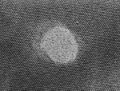
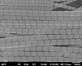
Latent ion trace in mica . Depending on the braking force of the projection, the track diameter is between 4 and 10 nanometers.

Molecular dynamics simulation of a collision cascade in gold. Development of a collision cascade with color-coded atomic kinetic energy triggered in the image center.

The trace etching threshold is the energy input that is required for the selective etching of the ion trace. In the case of ion crystals, the threshold increases with the thermal conductivity.


Etching process
One-step process
The selective etching of ion traces is closely related to the selective etching of grain boundaries and dislocation lines. The etching process must be slow enough to distinguish between the irradiated and non-irradiated material. The resulting shape depends on the type of material, the concentration of the etchant and the temperature of the etching bath. In crystals and glasses, the selective etching is based on the reduced density of the material in the ion track. In polymers, the selective etching depends on the fragmentation of the polymer in the core area of the ion track. The core area is surrounded by a partially cross-linked area of less etchability (halo). Outside the networked halo, the ion track grows linearly over time. The result of the selective etching is a depression, a pore or a channel.
The etching promoted by wetting agents is used to create track shapes . The method is based on the self-organization of monolayers on the inner wall of the etched channel. The monolayers are a barrier for the dissolved (solvated) ions in the aqueous medium. It hinders the etching of the surface. Depending on the concentration of the wetting agent and the etchant, barrel-shaped or cylindrical shapes are created. The technique is used to increase the aspect ratio.
Multi-stage process
The step-by-step irradiation and processing : A multi-stage process with two irradiations and two etchings for the production of perforated depressions.
Arbitrary irradiation angles force anisotropy along a certain axis of symmetry.
Multi-angle channels are mutually penetrating networks of two or more sets of channels in different directions.

Two-sided etching of an ion track at an etching rate ratio of 5: 1.
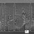
Asymmetrical channels with a constriction at the top.
Perforated micro containers .

Influence of the irradiation angle (45 and 90 degrees).
Channel overlap . Three membranes with crossing ion tracks (± 10, ± 20, ± 45 degrees).


| material | pH | Etching medium | Awareness 1) | Desensitization 2) | T / C 3) | Speed 4) | Selectivity 5) |
|---|---|---|---|---|---|---|---|
| Pc | basic | NaOH | UV | Alcohols | 50-80 | Fast | 100-10000 |
| PET | basic | NaOH | UV, DMF | Alcohols | 50-90 | Fast | 10-1000 |
| basic | K 2 CO 3 | 80 | Slowly | 1000 | |||
| PI | basic | NaOCl | NaOH | 50-80 | Fast | 100-1000 | |
| CR39 | basic | NaOH | UV | 50-80 | Fast | 10-1000 | |
| PVDF 6) | basic | KMnO 4 + NaOH | 80 | medium | 10-100 | ||
| PMMA 6) | angry | KMnO 4 + H 2 SO 4 | 50-80 | medium | 10 | ||
| PP 6) | angry | CrO 3 + H 2 SO 4 | 80 | Fast | 10-100 |
1) Sensitizers increase the track etch ratio by breaking chemical bonds and increasing the free volume.
2) Desensitizers reduce the trace etching ratio. Another option is heat treatment.
3) Typical range of the etching temperature. The etching rate increases with the concentration and temperature of the etching medium.
4) The axial etching depends on the track etching rate v t , the radial etching on the general etching rate v g .
5) Selectivity (aspect ratio, track etching ratio) = track etching speed / general etching speed = v t / v g .
6) The method requires the removal of the metal oxide remaining on the sample by hydrochloric acid.
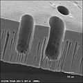
Impression
Etched ion traces can be molded using polymers or metals . The molded micro-parts can be used as a composite material . A replica can be separated from its shape mechanically or chemically. Polymer replicas are made by filling the etched ion track with a liquid precursor of the polymer and then curing it. Curing can be carried out catalytically, by UV radiation or by heat. Metal replicas can be made either by electroplating or electroless deposition. In order to mold through pores, a metal film is first deposited on the porous membrane, which serves as a cathode during electrodeposition. The membrane is then immersed in a suitable metal salt solution. The cathode film is negatively charged with respect to the anode. The anode is placed on the opposite side of the membrane. The solvated, positively charged metal atoms are drawn to the cathode. There they are neutralized by escaping electrons and deposited as a metal film. During electrodeposition, the channels fill with metal, starting with the applied cathode film. The length of the microwires can be specified by the duration of the deposition. A rapid deposition gives polycrystalline wires, a slow deposition gives a single crystalline wire. Free-standing replicas are produced after the deposition of a stable cathode layer by removing the template.
Interpenetrating networks of wires are made by electrodeposition into multi-angle irradiated etched membranes. In this way, free-standing 3D networks with adjustable penetration can be created.
Segmented nanowires are produced by alternating polarity reversal during the deposition. The segmentation length is controlled by the pulse duration of the deposition. In this way, the electrical, thermal and optical properties of the composite material can be adjusted.
Free-standing metal wires produced by electrical molding.

Mutually penetrating network of wires.
Bundle of segmented wires obtained by polarity reversal.


Applications
Filters : Filters with a uniform pore size and shape are among the first applications of ion track technology. They are offered by several manufacturers.
Size classification of microparticles and nanoparticles : The resistance of a channel filled with a saline solution depends on the volume of the particle slipping through the channel. This technique is used to determine the number and size of cells, bacteria and virus particles.
pH sensor : Channels filled with a salt solution have a "volume conductivity" and, in the case of an electrically charged surface, an additional "surface conductivity". The surface conductivity results from the fact that the ions bound to the wall of the channel attract a cloud of mobile ions of opposite charge. In this way an electrical double layer is formed . In the case of fine channels, the surface conductivity outweighs the volume conductivity. As a result, the electrical resistance of the channel is influenced by the interaction of the transported ions with the channel wall. This effect can be used in sensor technology. Negative surface charges can be occupied by relatively tightly bound protons. At low pH (high proton concentration) the wall charge is completely neutralized by protons. The channel becomes a pH sensor.
Electrically rectifying pores : Asymmetrical pores are achieved by etching the ion tracks embedded in the membrane on one side. The geometric asymmetry results in an asymmetry in the electrical conductivity. The phenomenon can be compared to an electric valve. The pore has two characteristic conductivity states: open and closed. The valve opens above a certain voltage. The valve closes below a certain voltage.
Thermoresponsive Channel : Made by lining a channel with thermoresponsive poly (N-isopropylacrylamide) gel.
Biosensor : The chemical modification of the channel changes its interaction with particles slipping through. Different cladding affects the passage time. In this sense, the channel wall "recognizes" the particle passing through. For example, DNA fragments are selectively bound to their complementary fragments. The attached molecules reduce the channel volume. The increased electrical resistance of the channel reflects the concentration of the "recognized" molecules.
pH sensor : Electrically negatively charged channels can be achieved through the selective etching of ion traces in polymers. If these are filled with a dilute salt solution, a positive, mobile counter-charge cloud forms near the surface. This increases the electrical conductivity of the channels. Since the wall charges are neutralized by protons, the conductivity depends on the proton concentration, the pH value, of the solution.
Anisotropic electrical conductivity : a metal plate studded with free-standing wires becomes a large-area field emitter.
Magnetic multilayers : Nanowires, which consist of alternating layers of magnetic and non-magnetic layers, act as magnetic field sensors. For example, cobalt-copper layers are obtained from a salt solution that contains the ions of both metals. At lower voltage the (nobler) copper is deposited while the more easily oxidizable (less noble) cobalt remains in the solution. At higher voltages, both metals, the copper and the cobalt, are separated out. If the concentration of cobalt in the salt solution is very high compared to copper, cobalt in particular is excreted at high voltage. A magnetically active layer is created. The magnetic order of the cobalt layers increases when the external magnetic field increases. The magnetic orientation is determined by the external field. The individual cobalt layers are magnetically oriented in parallel. In the absence of an external magnetic field, the preferred magnetic order is anti-parallel. Since the lower order state corresponds to a higher electrical resistance, it can be used as a magnetic field sensor. The effect is used in read / write heads on magnetic storage media ( GMR effect ).
Spintronics : A spin valve structure is formed from two magnetic layers of different thicknesses. The thick layer has higher magnetic stability than the thin layer. It is used as a polarizer. The thin layer serves as an analyzer. The electrical resistance depends on the mutual magnetic orientation of the layers. With a parallel order the resistance is small and with an anti-parallel order it is high.
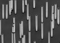
Textures : Tilted needle textures are coated with a water-repellent, Teflon-like film. They are super hydrophobic because water droplets only touch the tips. At the same time, the textures have a preferred transport direction due to the tilt. The possibility of converting vibration into translation was demonstrated.

Etched ion traces

Particle transit channel . The temporary current dip is proportional to the particle volume.
pH sensor : The electrical conductivity depends on the density of the mobile charge cloud.

The asymmetrical pore allows positive ions through preferentially from right to left.

Heat sensitive channel . The channel lined with hydrogel opens above and closes below the critical temperature.

Bio-specific sensor . The wall covering binds complementary biomolecules. The resistance increases with their concentration.

Field emitter arrangement

Layered magnetic field sensor . High field, parallel order, low electrical resistance.

Spin analyzer
The energy loss of spin-polarized electrons depends on the magnetic order of the analyzer. Left: polarizer (blue: spin up). Right: analyzer (blue: spin up; red: spin down).
Tilted track texture with asymmetrical sliding properties.


Individual evidence
- ^ DA Young: Etching of radiation damage in lithium fluoride . In: Nature . 182, No. 4632, 1958, pp. 375-377. bibcode : 1958Natur.182..375Y . doi : 10.1038 / 182375a0 . PMID 13577844 .
- ↑ a b c d e R.L. Fleischer, PB Price, RM Walker: Nuclear tracks in solids . University of California Press , 1975, ISBN 0-520-02665-9 .
- ↑ a b F. Seitz, JS Koehler: Solid State Physics . In: Academic Press . 1956, p. 307.
- ^ M. Toulemonde, C. Dufour, A. Meftah, E. Paumier: Transient thermal processes in heavy ion irradiation of crystalline inorganic insulators . In: Nuclear Instruments & Methods B . 166-167, 2000, pp. 903-912. bibcode : 2000NIMPB.166..903T . doi : 10.1016 / S0168-583X (99) 00799-5 .
- ↑ G. Remmert, Y. Eyal, BE Fischer, R. Spohr: Gas permeability and cross section of latent ion tracks in polymers . In: Nuclear Instruments and Methods B . 105, 1995, pp. 197-199. bibcode : 1995NIMPB.105..197R . doi : 10.1016 / 0168-583X (95) 00576-5 .
- ↑ a b W. D. Williams and N. Giordano: Fabrication of 80 Å metal wires . In: Review of Scientific Instruments . 55, No. 3, 1984, pp. 410-412. bibcode : 1984RScI ... 55..410W . doi : 10.1063 / 1.1137752 .
- ↑ R. Spohr: Ion tracks and microtechnology. . Vieweg Verlag , 1990, ISBN 3-528-06330-0 .
- ↑ a b R.L. Fleischer, PB Price and RM Walker: Method of forming fine holes of near atomic dimensions . In: Review of Scientific Instruments . 34, No. 5, 1963, pp. 510-512. bibcode : 1963RScI ... 34..510F . doi : 10.1063 / 1.1718419 .
- ↑ P. Apel: Swift ion effects in polymers: industrial applications . In: Nuclear Instruments and Methods in Physics Research Section B . 208, 2003, pp. 11-20. bibcode : 2003NIMPB.208 ... 11A . doi : 10.1016 / S0168-583X (03) 00634-7 .
- ↑ a b R.W. DeBlois, CP Bean: Counting and sizing of submicron particles by the resistive pulse technique . In: Review of Scientific Instruments . 41, No. 7, 1970, pp. 909-916. bibcode : 1970RScI ... 41..909D . doi : 10.1063 / 1.1684724 .
- ↑ a b W.J. Petzny, JA Quinn: Calibrated membranes with coated pore walls . In: Science . 166, No. 3906, 1969, pp. 751-753. bibcode : 1969Sci ... 166..751P . doi : 10.1126 / science.166.3906.751 .
- ↑ a b G.E. Possin: A method for forming very small diameter wires . In: Review of Scientific Instruments . 41, No. 5, 1970, pp. 772-774. bibcode : 1970RScI ... 41..772P . doi : 10.1063 / 1.1684640 .
- ↑ J. Vetter: Detached metal whisker . GSI Darmstadt . Retrieved April 27, 2010.
- ^ Y. Eyal, K. Gassan: Observation of latent heavy-ion tracks in polyimide by means of transmission electron microscopy . In: Nuclear Instruments and Methods in Physics Research B . 156, No. 1-4, 1999, pp. 183-190. bibcode : 1999NIMPB.156..183E . doi : 10.1016 / S0168-583X (99) 00269-4 .
- ↑ JF Ziegler: Handbook of Stopping Cross-Sections for Energetic Ions in All Elements . Pergamon Press , 1980.
- ↑ Stopping and Range Calculation . Srim.org. Retrieved January 21, 2013.
- ↑ M. Lindeberg, K. Hjort: A comprehensive study of ion track enabled high aspect ratio microstructures in flexible circuit boards . In: Microsystem Technologies . 10, No. 8-9, 2004, pp. 608-621. doi : 10.1007 / s00542-003-0339-2 .
- ^ R. Spohr, G. Sharma, P. Forsberg, M. Karlsson, A. Hallén, L. Westerberg: Stroke Asymmetry of Tilted Superhydrophobic Ion Track Textures . In: Langmuir . 26, No. 9, 2010, pp. 6790-6796. doi : 10.1021 / la904137t .
- ↑ C. Riedel, R. Spohr: Transmission Properties of Nuclear Track Filters . In: Journal of Membrane Science . 7, No. 2, 1980, pp. 225-234. doi : 10.1016 / S0376-7388 (00) 80083-6 .
- ^ R. Spohr, C. Zet, BE Fischer, H. Kiesewetter, P. Apel, I. Gunko, L. Westerberg: Controlled fabrication of ion track nanowires and channels . In: Nuclear Instruments and Methods in Physics Research B . 268, No. 6, 2010, pp. 676-686. bibcode : 2010NIMPB.268..676S . doi : 10.1016 / j.nimb.2009.12.017 .
- ↑ a b B.E. Fischer, M. Heiss, M. Cholewa: About the art to shoot with single ions . In: Nuclear Instruments and Methods in Physics Research B . 210, 2003, pp. 285-291. bibcode : 2003NIMPB.210..285F . doi : 10.1016 / S0168-583X (03) 01038-3 .
- ↑ Table of nuclides . Atom.kaeri.re.kr. Retrieved January 21, 2013.
- ↑ Interactive Chart of Nuclides . Nndc.bnl.gov. Retrieved January 21, 2013.
- ↑ 10 2 fission events / s
- ↑ Brookhaven Tandem Van de Graaf
- ^ GSI Irradiation Facilities
- ^ High Volume Accelerator Systems . Highvolteng.com. Retrieved January 21, 2013.
- ^ Estimate Coulomb barrier . Physicsconsult.de. Retrieved January 21, 2013.
- ↑ For iron, the mass ratio M Fe / m e is ≈ 10 5
- ^ RL Fleischer, PB Price, RM Walker: Ion Explosion Spike Mechanism for Formation of Charged Particle Tracks In Solids . In: Journal of Applied Physics . 36, No. 11, 1965, pp. 3645-3652. bibcode : 1965JAP .... 36.3645F . doi : 10.1063 / 1.1703059 .
- ↑ K. Nordlund, M. Ghaly, RS Averback, M. Caturla, T. Diaz de la Rubia, J. Tarus: Defect production in collision cascades in elemental semiconductors and FCC metals . In: Physical Review B . 57, No. 13, 1998, p. 7556. bibcode : 1998PhRvB..57.7556N . doi : 10.1103 / PhysRevB.57.7556 .
- ^ R. Katz: Track Structure Theory In Radiobiology and In Radiation Detection . In: Nuclear Track Detection . 2, No. 1, 1978, pp. 1-28. doi : 10.1016 / 0145-224X (78) 90002-9 .
- ^ M. Toulemonde, Ch. Dufour, A. Meftah, E. Paumier: Transient thermal processes in heavy ion irradiation of crystalline inorganic insulators . In: Nuclear Instruments and Methods in Physics Research Section B: Beam Interactions with Materials and Atoms . tape 166-167 , May 2, 2000, pp. 903-912 , doi : 10.1016 / S0168-583X (99) 00799-5 .
- ↑ PYApel, IV Blonskaya, AY Didyk, SN Dmitriev, OL Orelovitch, D. Root, LI Samoilova, VA Vutsadakis: Surfactant-enhanced control of track-etch pore morphology . In: Nuclear Instruments and Methods in Physics Research, B . 179, 2001, pp. 55-62. bibcode : 2001NIMPB.179 ... 55A . doi : 10.1016 / S0168-583X (00) 00691-1 .
- ↑ LCT Man, P. Apel, T. Cheung, L. Westerberg, KN Yu, C. Zet, R. Spohr: Influence of a surfactant on single ion track etching. Preparing and manipulating individual cylindrical micro wires . In: Nuclear Instruments and Methods in Physics Research, B . 265, No. 2, 2007, pp. 621-625. bibcode : 2007NIMPB.265..621M . doi : 10.1016 / j.nimb.2007.09.029 .
- ↑ P. Apel, R. Spohr: Introduction to ion track etching in polymers . Ion-tracks.de. Retrieved January 21, 2013.
- Jump up ↑ PB Price, GM Comstock, RL Fleischer, WR Giard, HR Hart, GE Nichols: Cosmic-Ray Tracks in Plastics: The Apollo Helmet Dosimetry Experiment . In: Science Journal . 172, No. 3979, 1971, pp. 154-157. bibcode : 1971Sci ... 172..154C . doi : 10.1126 / science.172.3979.154 .
- ↑ Electroplating
- ↑ M. Rauber, I. Alber, S. Müller, R. Neumann, O. Picht, C. Roth, A. Schöckel, ME Toimil-Molares, W. Ensinger: Highly-Ordered Supportless Three-Dimensional Nanowire Networks with Tunable Complexity and Interwire Connectivity for Device Integration . In: Nano Letters . 11, No. 6, 2011, pp. 2304-2310. bibcode : 2011NanoL..11.2304R . doi : 10.1021 / nl2005516 .
- ↑ M. Rauber, J. Brötz, J. Duan, J. Liu, S. Müller, R. Neumann, O. Picht, ME Toimil-Molares, W. Ensinger: Segmented All-Platinum Nanowires with Controlled Morphology through Manipulation of the Local Electrolyte Distribution in Fluidic Nanochannels during Electrodeposition . In: Journal of Physical Chemistry C . 114, No. 51, 2010, pp. 22502-22507. doi : 10.1021 / jp108889c .
- ↑ Ion-track companies . Physicsconsult.de. July 4, 2011. Retrieved January 21, 2013.
- ↑ A. Wolf, N. Reber, P. Yu. Apel, BE Fischer, R. Spohr: Electrolyte transport in charged single ion track capillaries . In: Nuclear Instruments and Methods in Physics Research B . 105, 1995, pp. 291-293. doi : 10.1016 / 0168-583X (95) 00577-3 .
- ↑ PY Apel, YE Korchev, Z. Siwy, Z .; R. Spohr, M. Yoshida: Diode-like single-ion track membrane prepared by electro-stopping . In: Nuclear Instruments and Methods in Physics Research B . 184, No. 3, 2001, pp. 337-346. bibcode : 2001NIMPB.184..337A . doi : 10.1016 / S0168-583X (01) 00722-4 .
- ↑ P. Ramirez, P.Yu. Apel, J. Cervera, S. Mafe: Pore structure and function of synthetic nanopores with fixed charges: tip shape and rectification properties . In: Nanotechnology . 19, No. 31, 2008, p. 315707. bibcode : 2008Nanot..19E5707R . doi : 10.1088 / 0957-4484 / 19/31/315707 .
- ↑ M. Tamada, M. Yoshida, M. Asano, H. Omichi, R. Katakai, R. Spohr, J. Vetter: Thermo-response of ion track pores in copolymer films of methacryloyl-L-alanine methyl ester and diethyleneglycol-bis- allyl carbonate (CR-39) . In: polymer . 33, No. 15, 1992, pp. 3169-3172. doi : 10.1016 / 0032-3861 (92) 90230-T .
- ^ LT Sexton, LP Horne, CR Martin: Developing synthetic conical nanopores for biosensing applications . In: Molecular BioSystems . 3, No. 10, 2007, pp. 667-685. doi : 10.1039 / b708725j .
- ↑ F. Maurer, A. Dangwal, D. Lysenkov, G. Müller, ME Toimil-Molar, C. Trautmann, J. Brötz, H. Fuess: Field emission of copper nanowires grown in polymer ion-track membranes . In: Nuclear Instruments and Methods in Physics Research B . 245, 2006, pp. 337-341. bibcode : 2006NIMPB.245..337M . doi : 10.1016 / j.nimb.2005.11.124 .
- ↑ L. Piraux, JM George, JF Despres, C. Leroy, E. Ferain, R. Legras, K. Ounadjela, A. Fert: Giant magnetoresistance in magnetic multilayered nanowires . In: Applied Physics Letters . 65, No. 19, 1994, pp. 2484-2486. bibcode : 1994ApPhL..65.2484P . doi : 10.1063 / 1.112672 .
- ↑ B. Doudin, JP Ansermet: Nanostructuring materials for spin electronics . In: Europhysics News . 28, No. 1, 1997, pp. 14-17.
- ↑ Converting vibration into translation ( MP4 ; 5.0 MB) Retrieved January 21, 2013.