Artificial rods

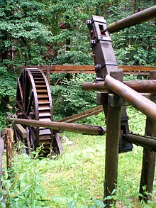
The art linkage , also rod drive , rack art or bar line is an invention of the mining , which served to mechanical motion by a Kunstrad to transmit is generated over smaller distances. For example, the Schwalheimer wheel with a 170-meter-long rest of the linkage is still functional today . A replica of an artificial rod can be seen in Bad Kösen an der Saale, for example, a reconstructed artificial wheel that was used to drive the rod is in Clausthal-Zellerfeld in the Upper Harz Mountains .
Basics
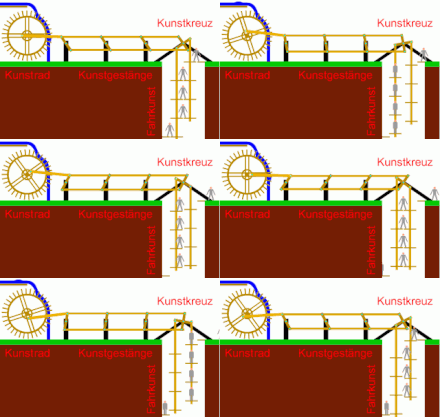
The artificial linkage dates back to before the invention of the steam engine and electricity . With the artificial linkage it was possible to exercise driving skills and pumping skills , although the available water wheel (artificial wheel) did not perform a pendulum movement, but a rotary movement. So that the artificial linkage could be set in a pendulum motion, a direction of movement had to be reversed using specially shaped linkage parts. The parts of the artificial rods that were installed in the shaft were called shaft rods or lifting rods. Artificial rods mounted in lines were called line rods. The field linkage was used for power transmission over greater distances between the drive machine and the lifting linkage. Rings made of iron attached to the wheel shafts, the attachment tubes and clip-on keels, but also to other parts of the wooden artificial rods are called artificial rings. Artificial rods are the long square timbers that were used to set the work of art in motion. The assemblies of the artificial rods are called artificial locks or rod locks. They are designed with interlocking so that the rods can be inserted into one another and fixed with bolts or screws.
The lifting linkage

The lifting rod runs vertically in the artificial shaft in order to transfer the force to the individual pump sets. It consists of about 19 to 20 centimeters thick, square spruce timber. The squared timbers are toothed at the ends and are connected to one another with appropriately toothed wooden straps. The wooden straps are pressed firmly to the lifting rod ends with synthetic rings. In addition, the artificial rings are secured against displacement with bolts inserted through them. At certain intervals there are hook arms attached to the side that are used to hang the piston rods. So that the horizontal movement of the field rod becomes a vertical movement, the lifting rod is attached to an artificial cross. The connection to the art cross is via an art lock. As a rule, two lifting rods are used for even loading, which results in mutual load balancing.
The field linkage

The field linkage was used to direct the power of the drive machine over greater distances to the synthetic sets of the shaft linkage. This was necessary when the drive machine could not be positioned above or immediately next to the shaft. A field linkage has the disadvantage that there are additional losses because of the large mass to be moved. The interposed field linkage results in a stroke loss of 25 to 50 percent due to the back and forth movement in the linkage connections (locks). In addition, additional timber is required for the construction of a field linkage. Due to the weather, this is very maintenance-intensive, so that additional staff was required to check and maintain the field linkage. The field poles consisted of several wooden artificial poles, which were provided with iron fittings. So-called artificial locks were located at the ends of the lateral artificial rods. These were cut and fitted in such a way that one pole could be pegged into the other pole. This was necessary so that the artificial rods could not slide apart when moving back and forth or when moving up and down.
There were two types of boom: boom with rollers and boom with rocker. In the field boom with rollers, the boom is moved on rollers. The rollers consist of eight to ten inches thick round timber, the lower side of which is firmly inserted into the earth and fixed with struts. In order to reduce friction, the linkage in the area of the individual rollers is provided with a beech wood drag rail over a complete stroke length. The field linkage with wings consists of a large wing, the so-called Wagbaum, of several small wings, the field poles, and the so-called Löcken with road trees. In the middle of the main swing arm there is a continuous peg on which it moves in the paw iron. At the two ends of the main wing there are several holes in which eye irons fastened with iron rings are inserted. In each eye iron there are up to three eyes, into which the basket rod is attached on one side and the field rod on the other. To make the stroke variable, several eyes are attached. To make the stroke longer or shorter, the basket rod is attached accordingly. The swing arms of the smaller swing arms are used to adapt the field linkage accordingly. This adjustment is necessary because the field linkage would otherwise break easily due to its length. The so-called loops are raised pads for the wings. They are set up every 2 to 3 fathoms and have crooked poles at the top - the so-called cuttings. The holes are provided with spreaders and pad blocks in such a way that the pole is adjusted in height so that the field poles can move in a straight line. All pins on the rocker arms are adjusted so that they are the same distance from both.
Direction of movement reversal

When reversing the movement from the rotary movement to the horizontal or vertical movement, but also from the horizontal movement to the vertical movement, specially shaped rod parts were used: on the one hand the crooked pin and on the other hand the artificial cross .
The crooked pin is a rod part that is bent at a right angle and serves as a continuation of the shaft journal. Its job is to transform the rotation of the water wheel into a horizontal or vertical movement. The so-called basket or blue rod was located on the crooked pin. With the crooked pin , the rotational movement of the artificial wheel was transferred to the field linkage or the shaft linkage, which then performs pendulum movements. The function of the crooked pin is very similar to the function of today's crankshaft and the connecting rod to the function of a connecting rod .
The artificial cross , also called break clamp , artificial angle or simply cross , consists of a strong wooden angle lever. The artificial cross was either attached directly to the basket rod of the crooked pin or connected to it via a field linkage. There were three different types of artificial crosses. Depending on the construction, they were referred to as whole artificial crosses, half artificial crosses or quarter crosses. The whole artificial cross is a cross with four arms. Of these arms, two opposing arms are connected to the shaft linkage and the other two arms are connected to the field linkage. The half cross is a cross with three arms. Two arms are horizontal, the third is upright. The shaft rod was connected to the two horizontal arms and the basket rod to the third arm. With the quarter cross, one arm is connected to the linkage and one arm to the blue rod.
The use of artificial crosses was essential for redirecting forces for various reasons. Even if the artificial wheel was mounted directly above the artificial shaft, the direct attachment of the shaft rods to the crooked pin created a very high load on the so-called crank lugs. The friction with direct assembly was also much greater. In addition, the shaft rods never produced a completely "clean" vertical movement, but instead swung back and forth a little laterally.
Existing systems

- Functional water art with wooden pendulum double rods of the graduation tower in Bad Kösen , Saxony-Anhalt, see: Water arts for graduation works
Significant assets lost
- Heller Wasserkunst , Selketal , Saxony-Anhalt
Individual evidence
- ↑ a b Mining dictionary. Bey Johann Christoph Stößel, Chemnitz 1778.
- ↑ Blue ribbon through Saxony-Anhalt: Bad Kösen (last accessed on September 1, 2013)
- ^ A b c Franz Adolf Fürer: Salt mining and salt mining. Printed and published by Friedrich Vieweg and Son, Braunschweig 1900.
- ^ Report on the mining industry. Bey Siegfried Leberecht Crusius, Leipzig 1772.
- ^ Carl Friedrich Richter: Latest mountain and hut lexicon. First volume, Kleefeldsche Buchhandlung, Leipzig 1805.
- ↑ a b Joh. Jos. Prechtl (Hrsg.): Technological encyclopedia or alphabetical handbook of technology, technical chemistry and mechanical engineering. Fifth volume, published by JG Gotta'schen Buchhandlung, Stuttgart 1834.
- ^ Carl Stegmayer: Manual of mining art for everyone. Publishing house by JL Kober, Prague 1862.
- ↑ Carl von Scheuchenstuel : IDIOTICON the Austrian mining and metallurgy language. kk court bookseller Wilhelm Braumüller, Vienna 1856.
- ^ Heinrich Veith: German mountain dictionary with evidence. Published by Wilhelm Gottlieb Korn, Breslau 1871.
- ↑ Johann Heinrich Moritz Poppe: Encyclopedia of the entire mechanical engineering, or complete instruction in practical mechanics and machine theory. Third part, by Georg Voss, Leipzig 1806.
Web links
- Das Huttaler Wasserregal Description of the water area in the Harz. GeoMuseum TU Clausthal (last accessed on April 9, 2015)


