Air line (high frequency technology)
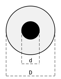
As air line ( English air line ) is referred to in the radio frequency technique one usually produced particularly precisely coaxially assembled electrical line that does not for holding the inner conductor dielectric supports, but only air contains.
principle
In this way, a highly accurate realization of the line wave resistance ( impedance ) Z L , which is based on the very precisely known permittivity of air (the relative permittivity ε r of air under normal conditions is about ε r ≈ 1,00059 ), apart from the precisely known wave resistance of the Vacuum Z 0 can be calculated solely from the mechanical dimensions D (inner diameter of the outer conductor tube) and d (diameter of the inner conductor rod) of the line.
The line impedance of a coaxial air line is calculated approximately as follows:
Applications
With the precise manufacture of outer and inner conductors, which can be manufactured with tolerances of a few micrometers (µm), an air line is obtained whose impedance deviates by less than 0.1 Ω from the desired reference value (usually 50 Ω). The air line is used in high-frequency measurement technology as an impedance standard with a particularly low reflection factor , for example for checking ( verifying ) the measurement accuracy of measurement devices.
The reflection factor r of the air line can be calculated from its line wave resistance (impedance) Z L and the reference impedance (e.g. 50 Ω):
Typical reflection factors of high quality ductwork are between 0.2% and 0.5%. Converted to return loss a ( return loss )
the result is values between 46 dB (0.5%) and 54 dB (0.2%).

Air lines can be used in a very large frequency range from around 1 GHz up to over 50 GHz (depending on the connection types ) and are commercially available. At low frequencies, their range of application is limited by the skin effect . Due to the finite conductivity of the conductor materials used (mostly gold with a specific conductivity σ ≈ 45 · 10 6 S / m on the surface ), the depth of penetration of the electromagnetic waves increases towards low frequencies. This leads to an effective increase in the (electrical) diameter difference between the outer and inner conductors and thus to an increase in the impedance of the air line. At 3 GHz, this is already around 20 mΩ and increases in inverse proportion to the square root of the frequency as the frequency falls. An important quality feature of air ducts is the low surface roughness of the order of less than one micrometer (<1 µm). The typical length of an air line is 300 mm.
Coaxial air lines are also made of wire in large dimensions in order to transmit high power in the long wave and medium wave range , for example between the broadcasting house and the broadcast mast (picture) . They are known as trap pipes .
There are also non-coaxial air lines. An example are coplanar air lines that are used in the test probes of wafer probes .
Web links
- Modeling of multi-coated, coaxial air ducts. Department message of the PTB , 2014, accessed on May 2, 2018.
- Math-assisted calibration of vector network analyzers (using a precision air line). PTB department news, 2008, accessed on May 2, 2018.
- Air line from Rosenberger Hochfrequenztechnik with 2.92 mm connectors , accessed on May 2, 2018.
Individual evidence
- ↑ Meinke / Gundlach : Taschenbuch der Hochfrequenztechnik , Volume 1 - Basics, Springer , 1992, p. 36. ISBN 3-540-54714-2 .
- ↑ Operation and Maintenance Manual for Air Lines by Anritsu , 1990, p. 1. PDF; 85 kB (English), accessed on May 3, 2018.
- ↑ Mathematics-based calibration of vector network analyzers (using a precision air line). PTB department news, 2008, accessed on May 2, 2018.
- ↑ Air line up to 40 GHz from Rosenberger Hochfrequenztechnik, accessed on May 2, 2018.
- ↑ Operation and Maintenance Manual for Air Lines by Anritsu, 1990, p. 1. PDF; 85 kB (English), accessed on May 3, 2018.


