
Mercedes-Benz OM 67
| Daimler-Benz AG | |
|---|---|
| Image does not exist |
|
| OM 67 | |
| Production period: | 1935-1954 |
| Manufacturer: | Daimler-Benz AG |
| Working principle: | diesel |
| Motor design: | R6 |
| Valve control: | OHV |
| Displacement: | 7274-7413 cm 3 |
| Mixture preparation: | Pre-chamber injection |
| Engine charging: | no |
| Power: | 70-88 kW |
| Dimensions: | 780 kg |
| Previous model: | OM 5 |
| Successor: | OM 315 |
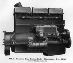
The Mercedes-Benz OM 67 is a diesel engine from Daimler-Benz AG that was developed for heavy commercial vehicles.


technology
The OM 67 is an uncharged in- line six - cylinder four - stroke diesel engine with pre-chamber injection , pressure circulation lubrication and water cooling. It is suitable for operation with crude oil. Several prototypes were made. The first type OM 67 has a 110 mm bore and 130 mm stroke, the displacement is 7413 cm 3 . The capacity is 95 hp (70 kW ) at 2000 min -1 indicated. This three cylinder head engine was built from 1935 to 1938. The original OM 67 was replaced by the OM 67/3 by 1937 at the latest, with an output of 74 kW. The most important differences are a changed bore-to-stroke ratio, a crankshaft with seven bearings instead of four, and different cylinder heads; the OM 67/3 only has two cylinder heads. With a cylinder bore of 105 mm and a piston stroke of 140 mm, the displacement is 7274 cm 3 . This was followed by the engine model 1939 OM 67/4 , in which the power to 112 horsepower (82 kW) at 2250 min -1 was raised. The subsequent model OM 67/8 provides 120 hp (88 kW) at 2250 min -1 . The OM 67/8 type is described in more detail below.
Crankcase
The crankcase of the OM 67 is divided into two parts, the upper part and the lower part. The lower part begins below the horizontal center of the crankshaft and is made of cast light metal. The oil pan is below the two front cylinders. The upper part of the crankcase is made of gray cast iron , the cylinders are cast into it. Since the engine has two cylinder heads for three cylinders each, the distance between the third and fourth cylinder is greater than between the other cylinders. The camshaft is located on the right-hand side of the upper part . It is driven by the crankshaft via a spur gear that engages directly in the camshaft spur gear ; the spur gears are located in a gear box cast onto the crankcase and are accessible from the outside behind a light metal cover . A flange for the gearbox is cast on the flywheel side , which surrounds the flywheel . Brackets for the alternator , injection pump , starter and water pump are also cast onto the upper part of the crankcase.
Pistons and power transmission
The pistons of the OM 67 are made of an aluminum - silicon alloy and have a flat piston bowl that is inclined towards the antechamber . They have four compression rings and an oil control ring. The pistons transmit the power to forged connecting rods made of chrome molybdenum steel with an I-shaped shaft. The connecting rod bearings are filled with lead bronze . The crankshaft, also made of chromium molybdenum steel forged, is stored for seven times in the crankcase, the crankshaft bearing flywheel side and the middle, formed as a ball bearing crankshaft bearings are wider than the rest. At the front end of the crankshaft, a friction vibration damper is attached to a cone outside the crankcase , to which the belt pulley for the fan and alternator drive is attached .
Cylinder head
The OM 67 has one cylinder head for every three cylinders, which is cast from light metal. The antechambers are inclined at approx. 45 ° to the combustion chamber, into which the fuel is injected. The injection nozzles are located in the antechambers in the cylinder head and are easily accessible from the outside. The same applies to the glow plugs , which are screwed horizontally below the injection nozzles into the cylinder head. The bumpers for the valve train, which are common in an OHV engine , are guided through the cylinder head on the OM 67 on the antechamber side. The exhaust ports of all cylinders opposite the prechamber open into a common exhaust manifold for all six cylinders. The intake combustion air passes through two wet air filters and the two longitudinally divided cylinder head covers into the intake ducts on the top of the cylinder head. The intake ports are on the same side as the exhaust manifold.
Valve train and engine control
The camshaft in the crankcase is driven directly by the crankshaft. A gear that drives the injection pump is flanged to the camshaft gear. In the middle of the camshaft is a drive wheel for the engine's oil pump. The valves hanging in the cylinder head are actuated by the camshaft via push rods and rocker arms. The rocker arms mounted in bronze bearings on the bracket are connected to the pressure lubrication system . A Bosch in- line injection pump size B , which is driven by the camshaft via the aforementioned gear, delivers the fuel to the injection nozzles. The injection pump has a centrifugal governor that limits the top speed. The position of the injection pump is chosen so that an air compressor for the brake system can be installed next to it.
Lubrication and ancillary equipment
The oil pump driven by the camshaft is flanged to the crankcase. It sucks the oil out of the oil sump and presses it through a sieve filter to feed it to the main oil line. The water pump is attached to the center of the engine's exhaust side. It is powered by the 12 volt / 300 W alternator. The water pump, alternator and cooling fan are driven by a common V-belt.
Technical specifications
| Parameters | OM 67 | OM 67/3 | OM 67/4 | OM 67/8 |
|---|---|---|---|---|
| Engine design | Six-cylinder in-line engine | |||
| Working principle | diesel | |||
| Mixture preparation | Pre-chamber injection | |||
| Valve control |
OHV valve control , 1 × inlet, 1 × outlet valve |
|||
| Bore × stroke | 110 × 130 mm | 105 × 140 mm | ||
| Displacement | 7413 cm 3 | 7274 | ||
| Rated speed | 2000 min -1 | ? | 2250 min -1 | |
| Nominal power at nominal speed | 95 PS / 70 kW | 100 PS / 74 kW | 112 hp / 82 kW | 120 PS / 88 kW |
| Maximum torque | 38 kp m / 373 N m at 1300 min −1 | ? | ? | 38 kp · m / 373 N · m at 1300–2250 min −1 |
| Firing order | 1-5-3-6-2-4 | |||
| Medium work pressure | 5.66 bar | ? | 6.0 bar | 6.5 bar |
| Compression ratio | 17: 1 | ? | ? | 20: 1 |
| Oil content | 12 l | ? | ? | 14 l |
| Dimensions | 650 kg | ? | ? | 780 kg |
| Medium piston speed | 8.7 m / s | ? | 10.5 m / s | 10.5 m / s |
| Fuel consumption | 258-272 g / kWh | ? | ? | ? |
| Lube oil consumption | 5.4 g / kWh | ? | ? | ? |
literature
- H. Kremser: The structure of high-speed internal combustion engines for motor vehicles and railcars . In: Hans List (Ed.): The internal combustion engine . tape 11 . Springer, Vienna 1942, ISBN 978-3-7091-5016-0 , p. 150–154 , doi : 10.1007 / 978-3-7091-5016-0 ( limited preview in Google book search).
Individual evidence
- ↑ a b Technical data OM 67
- ^ A b c Frank, Reinhard: Mercedes in the war - passenger cars, trucks, special bodies. Podzun-Pallas-Verlag, Dorheim. 1985. ISBN 3-7909-0244-6 . Page 49, Technical data Mercedes-Benz LG 3000 and Mercedes-Benz L 4500
- ^ Moving forward with traction: Daimler-Benz AG
- ↑ Chassis of the four-axle Mercedes-Benz LG 3000a with eight-wheel drive and a 100 hp diesel engine (approx. 1937/38).
Web links
- Picture of the engine OM 67 (7.4 l, 70 kW)
- Mercedes-Benz chassis LG 65/4, clearly visible OM 67/3 (7.3 l, 74 kW)
- Engine details
| Timeline of the Daimler-Benz diesel engines up to 1945 | |||||||||||||||||||||||||||||
|---|---|---|---|---|---|---|---|---|---|---|---|---|---|---|---|---|---|---|---|---|---|---|---|---|---|---|---|---|---|
| Number of cylinders | design type | Displacement (l) | 1920s | 1930s | 1940s | ... | |||||||||||||||||||||||
| 0 | 1 | 2 | 3 | 4th | 5 | 6th | 7th | 8th | 9 | 0 | 1 | 2 | 3 | 4th | 5 | 6th | 7th | 8th | 9 | 0 | 1 | 2 | 3 | 4th | 5 | ||||
| 1 | Lying | 3.4 | OE engine | ||||||||||||||||||||||||||
| 4.2 | OE engine | ||||||||||||||||||||||||||||
| 2 | In-line engine | 5.7 | S6 engine | ||||||||||||||||||||||||||
| 4th | 2.6 | OM 138 | |||||||||||||||||||||||||||
| 3.8 | OM 59 | ||||||||||||||||||||||||||||
| 4.9 | OM 65 | ||||||||||||||||||||||||||||
| 8.8 | OB 2 | ||||||||||||||||||||||||||||
| 6th | 7.3 | OM 67 | |||||||||||||||||||||||||||
| 7.4 | OM 67 | ||||||||||||||||||||||||||||
| 8.6 | OM 5 | ||||||||||||||||||||||||||||
| 10.3 | OM 79 | ||||||||||||||||||||||||||||
| 11.3 | OM 57 | ||||||||||||||||||||||||||||
| 12.5 | |||||||||||||||||||||||||||||
| OM 54 | |||||||||||||||||||||||||||||
| 12 | Boxer engine | 30.2 | OM 807 | ||||||||||||||||||||||||||
| V engine | 30.5 | OM 85 | |||||||||||||||||||||||||||
| OM 86 | |||||||||||||||||||||||||||||
| Legend: | Benz engines | Daimler-Benz engines | |||||||||||||||||||||||||||