Arrow
The sweep estimates the angle between the wing and the aircraft lateral axis in the plan view . If it is measured at the leading edge of the wing, it is called the leading edge sweep, at the back analogous to the trailing edge sweep, from the wing root to the rear it is positive. Many flight characteristics are influenced by the sweep, especially in the high speed range.
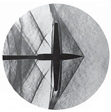
The first ideas to the positive wing sweep in connection with the supersonic flight has Adolf Busemann developed in 1935; Specific wind tunnel investigations and patent applications were made in 1939 by Albert Betz and his colleagues at the Aerodynamic Research Institute .
Positive arrow
No sweep or a slightly positive one is the norm in today's aircraft, the leading and trailing edges of the wings can be drawn backwards. Each wing has a certain aspect ratio, that is the ratio of the span to the mean wing depth. In the concept of the sweep, we first consider a constant wing cross section with an infinite span.
Constant wing cross section
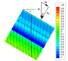
We think of a wing with a positive arrow pointing backwards, which has the same cross-section everywhere and an unlimited span. This wing is not pointed , so that there are no effects from the vicinity of the fuselage or the wing tip. The leading edge of the wing, the trailing edge and the line at a quarter of the wing depth are parallel and the three sweep angles are the same. The inflow velocity of the air can be broken down into a component perpendicular to the wing edge and a component tangentially (Figure 1), whereby the tangential component has no influence on the airflow.
The flow around the wing can be shown with a single, vertical section. Figure 2 shows the curved flow lines that intersect the cut surface and the air pressure in color. The flow variables in the cutting plane are three-dimensional, but only depend on two variables: the height above the lower edge of the wing and the depth in relation to the wing cross-section.
Since is smaller than , the lift , the lift gradient and the pressure resistance are reduced compared to an unearthed wing. These properties from the inclined flow towards the edge of the wing with the sliding angle are called cosine beta effects. With the swept wing, the wave resistance also decreases more than the lift. This increases the glide ratio of the wing and the critical Mach number in the case of transonic flow .
Cross-flow eddies lead to instability, because the laminar state changes into the turbulent on the swept wing. The influence of the two-dimensional Tollmien-Schlichting wave takes a back seat.
Finite stretch
With a real, finite wing, the sweep changes the lift distribution. At the beginning of the 20th century, the Horten brothers described this as a center effect .
- A positive sweep > 0 leads to an increase in lift in the outer area and to a reduction in the wing root.
- A negative arrow <0 conversely increases the lift in the inner area.
The deformation of the lift distribution increases the induced drag. A changed wing chord can compensate for this.
Positive swept wings lead on the one hand to increased directional stability as well as to a positive push-roll moment . The disadvantages are in the tear-off behavior, since c a max is reached first at the wing tip. The stall occurs first in the area of the ailerons and on the “rear” part of the wing. A second negative effect is the flow of boundary layer material towards the wing tip, which leads to a thickening of the boundary layer and a greater tendency to detach. Suitable countermeasures are boundary layer fences , saw teeth on the leading edge of the wing (see F-4 Phantom II ), twisting the wing and adapting the profile.
Real wings show a local de-arrowing of the lines with the same pressure at the wing root and in the vicinity of the edge arch. Because the isobars are for reasons of symmetry at the wing root perpendicular to the plane of symmetry. A real wing thus loses the advantages of the sweep in these areas. To compensate for this, the concept of “straight isobars” is implemented. The profile shape is adapted so that a straight isobar course is achieved over the entire span.
Finally, a positive swept wing has little gust sensitivity because the decreased increase in lift is directly proportional to the gust load. The arrow on a wing can vary, individual wing sections can be arrowed to different degrees.
Negative arrow

Since the beginning of the practical use of the arrow there are also constructions with negative arrow. As shown in the picture the air flow running in this wing geometry for hull down rather than away from the hull, as with conventional designs. This allows the air flow at wingtips and on the control surfaces can be much slower before the flow breaks off ( stall , Eng. Stall ) and the lift is lost. As a result, extraordinary maneuverability is achieved when the wings and control surfaces are positioned at a steep angle to the air flow. The aircraft has enough airflow over the rudder and elevator control surfaces even at low flight speeds . Therefore, in theory, this wing geometry would be suitable for extremely agile interceptors .
During the Second World War , research was carried out on aircraft with a negative wing arrow. However, the material loads were too high for practical use. Only recently have fiber composite materials exist for wings with negative sweep that can withstand high torsional and shear forces.
Gliders with this wing geometry are mainly two-seaters. For decades, the wing root, i.e. the connection to the fuselage, has been moved back so that the second seat can be placed in front of the spar .
Examples
The leading and trailing edges of the wings with a negative arrow:
- Cornelius XFG-1 , brushless cargo glider
- DFS 42 , test glider
- FTAG Esslingen E11 , two-seater glider for the investigation of extreme forward sweep
- Grumman X-29 , experimental aircraft
- HFB 320 , business jet
- Junkers Ju 287 , bomber prototype
- Soviet experimental bomber EF 140 , prototype
- SAT SR-10 , prototype, jet trainer
- Schleicher ASK 13 , glider
- Schleicher K 7 , glider
- Sukhoi Su-47 , experimental aircraft .
application

The optimal sweep of wings depends on the expected air flow velocity around the wings. Here a compromise has to be found between high lift at low speeds for take-off (low sweep) versus low flow resistance and low turbulence at cruising speed (strong sweep), with the aim of ensuring a laminar air flow over all control surfaces in all expected flight positions to reach. If you draw the air pressure and the associated speeds in a coordinate system, an imaginary area results within the lines in which the aircraft can be safely used. This envelope curve , known as the flight envelope , is different for each aircraft model and, along with many other factors, depends to a decisive extent on the wing geometry and thus on the sweep.
To simplify matters, two principles apply: Airplanes that mostly fly at low altitudes and at low speeds should be equipped without a sweep. Commercial aircraft that move transonic at high altitudes and fly in the medium speed range at sea level are given a medium arrow.
literature
- Adolf Busemann : Aerodynamic lift at supersonic speed. Lecture at the 5th Volta Conference in Rome, 1935.
- Ernst Götsch: Aircraft technology. Motorbuchverlag, Stuttgart 2009, ISBN 978-3-613-02912-5 .
Footnotes
- ↑ Werner Heinzerling: Wing sweep and area rule, two basic German patents of aircraft aerodynamics , Munich without a year, (Deutsches Museum). online (PDF; 10 MB)
- ^ Photo of FTAG E11 of Akaflieg of HS Esslingen
Web links
- Werner Heinzerling: Wing sweep and area rule (PDF; 10 MB)


