Parallel resonance
Parallel resonance , also known as current resonance , is the designation for the impedance maximum of electronic circuits in the vicinity of a resonance frequency. Parallel resonant circuits have only one resonance frequency, other circuits have several.
This high impedance is used in the trap circuit to block unwanted frequencies.
resonance
For the amount of the frequency-dependent impedance of a parallel connection of R, L and C, the following applies according to the principles of AC technology:
When the term becomes zero, the impedance of the parallel connection is a pure, real effective resistance to the outside :
The parallel resonance occurs
The above equation is called the resonance condition. From the resonance condition, the frequency at which the resonance occurs, the resonance frequency, can be determined by transforming and resolving . It results from Thomson's oscillation equation :
Further properties upon resonance
Resonance current
Due to the reactance of L and C, a further effect occurs at resonance. The following resonance currents pulsate between the two components:
The currents reach in the event that
Values that are greater than the external current driven by the terminal voltage . The alternative designation current resonance for parallel resonance results from this circuit property .
Phase angle
The phase angle ( phase shift ) at resonance is
so no phase shift, as the circuit behaves like a pure resistance.
Circular quality
The circular quality Q, also the quality factor , resonance exaggeration or resonance sharpness, is the reciprocal of the loss factor d. For the parallel connection of R, L and C one obtains:
This gives rise to the resonance currents
special cases
Parallel resonance of coils
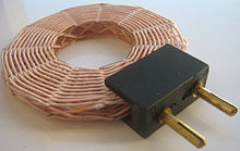
Coils not only have a low capacitance between the connecting wires, but also between the individual turns. Together with the inductances in between, a structure of distributed L and C is created which - similar to a dipole - has several resonance frequencies that can be calculated using the formulas of line theory .
If a long cylinder coil is fed with high-frequency current, an oscilloscope can be used to measure the voltage as a function of length. If this follows a function shown in the picture, there is parallel resonance although no capacitor can be seen. The total voltage between the coil ends is then very large, considerably greater than the calculated value of the inductive resistance.
The lowest resonance frequency can be increased with a special winding technique. In a cross- wound bobbin , the mean distance between successive turns is considerably greater than in the case of a conventional cylinder winding , which reduces the capacity of successive turns. Elongated, single-layer wound solenoids have the highest natural resonance frequency. With a large number of turns, such as the secondary coil of a Tesla transformer , however, it drops to around 500 kHz.
Parallel resonance with quartz crystals
In many electronic circuits, oscillating circuits are replaced by oscillating crystals because of their sometimes considerably better properties . Although - apart from parasitic properties - these crystals do not have any coils or capacitors, they show all properties of parallel resonance at very special frequencies; this is caused by the combination of piezoelectricity and mechanical resonance . As a result, unlike oscillating circuits, there is also resonance on (odd-numbered) harmonics . Starting from the lowest frequency, the resonance frequencies behave roughly like 1: 3: 5: 7 ... They are extremely stable and have significantly higher quality factors than resonant circuits, which is why quartz oscillators are used as clock generators in clocks and transmitters. All quartz crystals show series resonance at a slightly lower frequency.
Parallel resonance in lines
With devices in the radar range, the property of stub lines is used to transform the terminating resistor depending on the length L (see line theory ). Striplines are shortened because of the permittivity of the insulating substrate.
- If L = λ / 2 and one end is open, the other end also has high impedance. This applies unchanged if the wire length is doubled, tripled or generally n -folded ( n ∈ ℕ ).
- If L = λ / 4 and one end is connected to ground, parallel resonance, i.e. particularly high impedance, is measured at the other end. At this wavelength, the short piece of wire has the same high resistance as a parallel resonant circuit. This is used at very high frequency to support a line like an isolator, although that support conducts very well for direct current.


