
Quartz crystal

A quartz oscillator , often simply abbreviated as quartz , is an electronic component in quartz oscillators which is used to generate electrical oscillations at a specific frequency . Its operation is based on the principle of electro-mechanical resonance of the installed piezoelectric and electrodes provided quartz crystal .
Historical


Alexander M. Nicholson carried out the first systematic and scientifically documented experiments with electromechanical resonance oscillations in 1918 with naturally grown Seignette salt crystals . Just one year later, Walter Guyton Cady replaced the Seignette salt crystal with the more efficient quartz crystal that is still in use today.
The Bell Telephone Laboratories and other research institutions drove from 1923 to develop practicable oscillating crystals mainly for frequency stabilization in radio technology ahead and competed their use in various contemporary publications.
In 1928 Warren Marrison , an employee of Bell Telephone Laboratories, developed the first quartz-controlled clock that greatly increased the accuracy of timekeeping.
From 1934, less temperature-dependent quartz crystals could be manufactured for frequency stabilization with the help of refined crystal processing methods (so-called cuts ). However, the high sensitivity to moisture and the associated undesirable fluctuations in the resonance frequency could not be significantly reduced until the early 1950s through the use of closed metal or glass housings.
During the Second World War, the increased use of military radio technology led to an increased demand for quartz oscillators, which could no longer be met by natural quartz crystals alone and which led to the development of processes for the production of synthetic crystals. Quartz was synthesized on an industrial scale as early as 1948. Further refinements worth mentioning, especially with regard to the miniaturization of the crystals produced, were not achieved until 1968 by J. Staudte.
From the 1950s onwards, the controllable frequency range and thus also the range of application of the quartz crystal has been greatly expanded through the inclusion of so-called harmonics of the crystal. Since then, development has concentrated on reducing interference, i. H. on increasing the goodness.
General information on structure and function

The quartz crystal is provided with electrodes on both sides to which an alternating field generated by any oscillator is applied. The frequency of the alternating field is brought into agreement with the mechanical natural frequency of the quartz crystal by means of feedback . As a result, the quartz oscillator acts like an electrical resonance circuit with very little damping (= very high quality factor ). When used appropriately, crystal oscillators can achieve frequency accuracies that well exceed most industrial requirements.
The quartz oscillator carries out deformation oscillations (longitudinal, thickness shear or bending oscillations) in the alternating electric field if the frequency of the alternating field corresponds to the natural frequency of the quartz plate.
A quartz can be operated in series or parallel resonance. The two natural frequencies are very close together. The resonance frequency can also be slightly influenced by the external wiring. A trimmer with a few pF is often connected in series or parallel to the quartz (depending on whether the quartz is operated in series or parallel resonance) in order to compensate for manufacturing tolerances (“pulling” the quartz). The electrical circuit of these special oscillators is called a quartz oscillator .
The natural frequencies of the quartz are to a small extent dependent on the temperature . The temperature coefficient can, however, be influenced by selecting the quartz section (geometry in relation to the crystal axes) so that it can be kept very low for use as a time base . In order to keep frequency changes particularly small, the quartz oscillator can also be thermostated using a quartz furnace .
Basics
Properties of the quartz crystal

The basic material of an oscillating quartz is quartz, the crystalline form of silicon dioxide (SiO 2 ), which occurs naturally as rock crystal. Quartz crystals appear in a trigonal crystal system in two types, as "right" or "left quartz".
These two types are mirror images of each other. The cross-section of an ideal quartz crystal is hexagonal. As is usual in crystallography , the three mutually perpendicular axes are defined as x, y and z. The z-axis, also called the optical axis, goes through the tip of the crystal. The y-axis connects two opposite side surfaces of the crystal and is called the mechanical axis. The x-axis is the so-called electrical axis, because when the crystal is mechanically stressed, an electrical charge occurs in this direction ( piezoelectricity ). However, there are two crystal systems in quartz crystals, the hexagonal crystal system above 573 ° C, which is free of piezoelectric phenomena, and the trigonal crystal system below 573 ° C, the α-modification of the quartz crystal. Only the α-modification of quartz has piezoelectric properties.
The quartz crystal now becomes an oscillating quartz when a disk or a rectangular plate is cut out of the crystal in a precisely defined crystallographic orientation (quartz section). If this disc or plate is mechanically deformed, electrical charges are generated on its surface. This piezoelectric effect, the piezoelectricity, is also reversible, that is, if an electric field is applied to this material, it is deformed (inverse piezoelectric effect). As soon as the electric field is no longer present, the material takes on its original shape again, whereby an electric voltage is generated. The mechanical deformation on the piezoelectric crystal of an oscillating crystal, once caused by applying a voltage, generates an electrical signal after the voltage is switched off . By means of a feedback circuit , this signal can be used to generate a mechanical resonance vibration of the material, with a very stable clock signal due to the very good physical parameters of the silicon oxide - for example low damping of the crystalline material, extremely good mechanical and dynamic stability and the low temperature dependence with a precise frequency and a defined amplitude . The choice of the quartz cuts and the mechanical oscillation form that is excited in each case also result in typical electrical values of the quartz oscillators for certain frequency ranges.
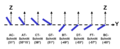
Waveforms
- Oscillation modes for crystals for quartz oscillators

Oscillation modes of quartz crystals

Deformation
vibrations of a thickness shear vibrator

A quartz plate cut out of a quartz crystal carries out deformation oscillations in the electric alternating field if the frequency of the alternating field corresponds to the natural frequency of the quartz plate. As with all mechanical oscillators, this case, the resonance , is determined by the material constants and the mechanical dimensions. The deformation vibrations of quartz resonators can occur in different mechanical vibration forms.
Length oscillators , also known as extensional oscillators, are plate-shaped resonators that oscillate in the direction of their longer dimensions. The change in length is caused by an alternating electric field that is perpendicular to the direction of oscillation. The oscillation that occurs can also be clearly described with an acoustic wave that is generated in the center of the resonator. This wave propagates in the longitudinal direction of the resonator. Total reflection of the wave takes place at the ends of the resonator . By superimposing the wave traveling back and forth, a standing wave is created in the case of resonance, provided the resonator length is a whole multiple of half the wavelength.
Flexural vibrations in the flexural oscillators can be excited by providing length oscillators with two electrodes connected in phase opposition, so that two opposing fields occur in the x direction. This forces a bend in the z-direction. The frequency constant of the mostly square crystal rods of flexural vibrators is determined by the material constants and the length l and width b of the resonator, so that no uniform numerical value can be given for flexural vibrators. Linear and flexural vibrators are used to generate lower frequencies below 1 MHz.
The tuning fork transducers are a special form of flexible oscillators . They can be explained with the picture of a bent rod that carries out bending vibrations. The frequency of tuning fork oscillators depends on the length and width of the prongs. Tuning fork transducers are mainly used to generate clock frequencies.
The vibrations in thickness shear vibrators result from displacements in opposite directions between the two larger surface areas. The or - in the case of harmonic crystals - the oscillation nodes are located within the resonator. A sophisticated ratio of the resonator diameter to the thickness of the crystal and to the size of the electrodes allows the vibration energy to be concentrated in the center of the resonator, so that the crystal can be held on the circumference of the resonator. Thickness shear vibrators are particularly stable against external influences due to the type of resonance. They are most often used in oscillating crystals in the form of the AT cut and are used for practically all frequencies from 1 MHz upwards. The resonators are operated in their fundamental wave up to about 20 to 30 MHz. Above 30 MHz to about 250 MHz, thickness shear oscillators are excited with their odd harmonic up to the 9th harmonic.
The resonance vibration in surface shear vibrators results from opposing displacements of two side surface areas in relation to each other. The resonance frequency of the surface shear vibrator is determined by the dimensions of the edge lengths of the mostly square or rectangular resonators and the direction-dependent elastic values of the crystal. This results in frequency constants N that are dependent on the crystal cut and have preferred frequency ranges.
Crystal cuts
The properties of quartz oscillators such as the thermal stability of the resonance frequency, the internal losses and the drawability are determined by the cutting angle with which the resonator plates are cut out of the quartz crystal. The direction of crystallization in a resonator plate is specified by the cutting angle, which influences the mechanical properties of the piezo crystal. This also applies to other components such as B. surface acoustic wave filters (English surface acoustic wave , SAW) that work with quartz crystals as the base material.
- Location of different crystal cuts in the quartz crystal

Position of the coordinates in the quartz crystal with representation of the position of the X and Y sections
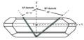
Position of the AT and BT cuts in the quartz crystal
Cutting angle of different crystal sections of quartz crystals


The position of the cuts in the quartz crystal is defined as an angle between X and Y and possibly also Z with the help of the geometric axes. Every special cut is marked with a letter combination, whereby a “T” in this combination always indicates a temperature-stabilized quartz crystal.
- Temperature-related frequency changes in quartz crystals with different crystal sections

Frequency changes as a function of the temperature for different crystal cuts
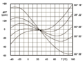
Frequency changes as a function of the temperature during the AT cut with slightly changed cutting angles


The main distinguishing feature of the different crystal cuts is the different dependence of the resonance frequency on the temperature. For this purpose, the upper left picture shows the frequency changes in the temperature range from −40 ° C to +120 ° C with different crystal sections. It can be seen that the crystal sections, with the exception of the AT section, have the curve shape of a parabola open at the bottom. At the apex of the parabola there is a more or less large temperature range in which the frequency change is relatively small. The AT cut, on the other hand, forms a sinusoidal or S-shaped curve of the frequency change over temperature. It can be placed in such a way that the curve progression at the turning point of the sine curve covers the temperature range from -40 ° C to +100 ° C in such a way that the frequency change Δf / f is less than ± 30 ppm, with the range at the turning point at around 25 up to 35 ° C and ideally there is almost no change in frequency. That is why more than 90% of all manufactured quartz crystals, with the exception of the tuning fork quartz, are made with AT-cut crystals.
For frequencies up to 10 MHz, the standard AT cut has an inclination angle of the crystal cut of 35 ° 15 'on the X-axis compared to the optical Z-axis (35 ° 18' for frequencies> 10 MHz). As the above picture on the right shows, the course of the curve can be significantly influenced with a small change in the cutting angle. This means that the upper turning point of the frequency change curve can be placed in the higher temperature range. By heating up the quartz crystal, the operating point can be set in this range so that the generated frequency is independent of the ambient temperature. This is used in the temperature-compensated oscillators TCXO and OCXO.

The frequency of a quartz crystal in the fundamental wave depends linearly in inverse proportion to the thickness of the plate. This means that the mechanically thinnest crystal section that can be produced determines the highest resonance frequency. This limit value is now (2010) around 50 µm. The frequency constant , that is the thickness of a plate that results in a resonance frequency of 1 MHz, is 1.661 mm for AT cuts, for example. This means that with a quartz plate thickness of 50 μm, a resonance frequency of around 30 MHz can be generated. However, structure etching of the cut crystal with the inverted mesa technique can reduce the thickness of a quartz plate to around 30 µm, so that an upper resonance frequency of the fundamental wave of 55.7 MHz can be achieved with this special manufacturing technique.
In addition to the thickness of a resonator, the external dimensions of the quartz plate or the quartz disk are an important factor. They determine the quality of the quartz crystal; the larger the dimensions of the resonator, the higher the quality factor.
In addition to the single rotated cuts through the crystal, cuts are also made that are rotated twice with respect to the X axis. These types of cuts are often intended for sensors.
| cut | Frequency range | Vibration mode |
Cutting angle | Hints |
|---|---|---|---|---|
| AT | 0.5–30 MHz (fundamental tone) 15 ... 75 MHz (3rd overtone) 50 ... 150 MHz (5th overtone) 100 ... 200 MHz (7th overtone) 150 ... 300 MHz (9th overtone) |
Thick shear oscillator |
35 ° 15 ′, 0 ° (<25 MHz) 35 ° 18 ′, 0 ° (> 10 MHz) |
The advantage of the AT cut is a low and almost linear temperature response of the resonance frequency at around 25 ... 35 ° C. AT resonators with an almost linear temperature dependence of the frequency at higher temperatures for temperature-compensated oscillators ( TCXO , OCXO ) can be produced by small changes in the cutting angle .
AT quartz crystals are sensitive to mechanical stresses caused by vibration, shock or temperature changes. |
| SC | 0.5 ... 200 MHz | Thick shear oscillator |
35 ° 15 ′, 21 ° 54 ′ Twisted twice |
SC cut (SC = Stress Compensated)
The advantages of the SC cut are low phase noise and low aging. The frequency response is almost linear at 95 ° C. Compared to AT resonators, SC resonators are less sensitive to mechanical loads caused by vibration, shock or temperature changes, have a higher quality in vacuum operation and are less sensitive to the effects of gravity. They are used in space travel and in GPS systems in temperature-compensated oscillators (TCXO, OCXO). |
| BT | 0.5 ... 200 MHz | Thick shear oscillator |
−49 ° 8 ′, 21 ° 54 ' | The BT cut has similar properties to the AT cut at 25 ° C.
Because of the thicker crystal platelets compared to the AT and SC sections, resonators for frequencies above 50 MHz in the fundamental tone can be produced in the BT section. |
| IT | Thick shear oscillator |
Twisted twice | The IT cut has similar properties to the SC cut.
The frequency response at 78 ° C is almost linear. IT resonators are used in temperature-compensated oscillators (TCXO, OCXO). |
|
| FC | Thick shear oscillator |
Twisted twice | The FC cut has similar properties to the SC cut.
The frequency response is almost linear at 52 ° C. Because this temperature is lower than with SC and IT cuts, the FC cut is the energy-saving version for temperature-compensated oscillators (TCXO, OCXO). |
|
| AK | Thick shear oscillator |
Twisted twice | The AK cut has a better temperature-frequency behavior than AT and BT cuts with a higher tolerance towards the crystal orientation than the AT, BT and SC cuts. | |
| CT | 300 ... 900 kHz | Area- shear schwinger |
38 °, 0 ° | The parabolic opening constant a between 0 and +90 ° C is around −0.05… −0.06 ppm / K².
Quartz crystals in the CT section are mostly used for low frequencies in the kHz range, most commonly for clock crystals and radio clock crystals. |
| DT | 75 ... 800 kHz | Area- shear schwinger |
−52 °, 0 ° | The parabolic opening constant a between −1 and +60 ° C is around −0.02 ppm / K². |
| SL | 400 ... 800 kHz | Area- shear schwinger |
−57 °, 0 ° | The parabolic opening constant a between −1 and +80 ° C is around −0.04 ppm / K². |
| GT | 0.1 ... 3 MHz | Length oscillator |
51 ° 7 ′ | The parabolic opening constant a between −25 and +75 ° C is almost zero. |
| E, 5 ° X | 50 ... 250 kHz | Length oscillator |
The E-cut has a very low temperature coefficient. It is used for quartz filters in the low frequency range. | |
| MT | 40 ... 200 kHz | |||
| ET | 66 ° 30 ′ | |||
| FT | −57 ° | |||
| NT | 8 ... 130 kHz | Flexural oscillator |
The parabolic opening constant between 10 and 50 ° C is around −0.05 ppm / K². | |
| XY, | 3 ... 85 kHz | Flexural oscillator, tuning fork oscillator |
The XY cut is the most widely used low frequency quartz crystal cut. It is smaller than other low frequency cuts, cheaper to manufacture, has a low impedance and a low Co / C1 ratio. The main application is the clock frequency 32.768 kHz. The parabolic opening constant a between 10 and 50 ° C is around 0.04 ppm / K². | |
| H | 8 ... 130 kHz | Flexural oscillator |
The H-cut is used for broadband filters. It has a linear temperature coefficient. | |
| J | 1 ... 12 kHz | Length- bending oscillator |
The J-cut consists of an interconnection of two quartz plates to form a resonator. The individual resonators are selected so that the two resonators have different resonance frequencies for a given electric field. This creates a very low-frequency superimposed resonance. | |
| RT | Twisted twice | - | ||
| SBTC | Twisted twice | - | ||
| TS | Twisted twice | - | ||
| X 30 ° | Twisted twice | - | ||
| LC | Thick shear oscillator |
11.17 ° / 9.39 ° Twisted double |
The LC section (LC = linear coefficient ) has a linear temperature coefficient. It can be used as a sensor in quartz thermometers. | |
| AC | 31 ° | The AC cut (coupling = 0) is characterized by low coupling to other oscillation modes and is free from discontinuities in the temperature response of the frequency. It can be used as a sensor in quartz thermometers. The temperature coefficient is 20 ppm / K. | ||
| BC | −60 ° | The BC cut can be used as a sensor in quartz thermometers. | ||
| NLSC | The NLSC cut can be used as a sensor in quartz thermometers. The temperature coefficient is 14 ppm / K. | |||
| Y | The Y-cut can be used as a sensor in quartz thermometers. The temperature coefficient is 90 ppm / K. | |||
| X | 10 ... 100 kHz 40 ... 200 kHz |
Flexural oscillator, extensional oscillator |
0 0 |
The X-cut was used in the first ultrasonic crystal oscillator in 1921 by WG Cady and in the first 50 kHz oscillator for clocks in 1927 by Horton and Marrison. The parabolic opening constant a between 0 and 45 ° C is 0.04 ppm / K². |

Frequency constant
The deformation vibrations that a quartz crystal executes when it resonates in an alternating electric field, when the frequency f of the alternating field matches the natural frequency of the quartz plate, is determined by the material constants and the mechanical dimensions, as is the case with all mechanical vibrators.

with and , where the dimension in the direction of vibration, ρ denotes the density and the modulus of elasticity.


The term
is generally called the frequency constant or vibration coefficient and, because of the directional dependence of the modulus of elasticity, depends on the cutting orientation. Each quartz cut has a certain frequency constant, which is decisive for the length of the resonator in the direction of oscillation, or in other words, the frequency of a quartz crystal in the fundamental wave depends linearly in inverse proportion to the thickness of the plate. This means that the mechanically thinnest crystal section that can be produced determines the highest resonance frequency. This limit value is now (2010) around 50 µm.

With the frequency constant of 1661 kHz · mm, for example for AT cuts, this means that a resonance frequency of about 30 MHz can be generated with a quartz plate thickness of 50 μm. However, structure etching of the cut crystal with the inverted mesa technique can reduce the thickness of a quartz plate to around 30 µm, so that with this special manufacturing technique an upper resonance frequency of the fundamental wave of 55.7 MHz can be achieved for AT quartz crystals . The following table gives an overview of the frequency constants of various quartz cuts:
| Waveform |
Frequency constant N = f · l |
Frequency range |
|---|---|---|
| Thickness shear oscillator, AT cut | 1661 kHz · mm | - |
| Thickness shear transducer, SC cut | 1797 kHz · mm | - |
| Thickness shear oscillator, component cut | 2536 kHz · mm | - |
| Length oscillator, GT cut | 2808 kHz · mm | - |
| Surface shear transducer, DT cut | 2070 kHz · mm | 180 to 350 kHz |
| Surface shear transducer, CT section | 3070 kHz · mm | 300 to 1000 kHz |
| Surface shear transducer, SL cut | 4600 kHz mm | 400 to 800 kHz |
Manufacturing
The production of quartz crystals takes place in several steps described below, which can be summarized in:
- Synthetic production of the quartz crystal
- Manufacture of the blanks
- Contact and assembly
Synthetic production of the quartz crystal

Originally quartz crystals were made from naturally occurring quartz crystals, also known as rock crystal. But the natural material often does not form an ideal crystal. Twinning (twin crystals) occur, these are adhesions within the crystal, the main axes of which do not coincide. Furthermore, such crystals can have growth interruptions, gas and liquid inclusions, so that in the industry with the naturally occurring crystals large series production is not possible. The crystals required for the production of quartz oscillators have therefore been synthetically produced according to the hydrothermal principle since the 1950s. The geological formation of quartz is simulated in vertical autoclaves.
The lower part of the autoclave is filled with a sodium hydroxide solution, in which finely divided natural quartz dissolves to saturation at around 400 ° C and 800 bar with formation of silica. By thermal convection the supersaturated solution flows into the upper part of the autoclave and crystallized therein at a temperature of about 400 ° C and 1000 to 1500 bar at present there quartz seed crystals (engl. Seed ) from. The cooled solution sinks back into the hotter area and absorbs silica again. A cycle is created which leads to the growth of quartz single crystals at a growth rate of about 0.2 to 1 mm per day. The crystal formation takes place predominantly on the Z-surface and is free from adhesions and twists. In general, the growth process takes about 40 to 80 days and yields single crystals about 200 mm long and up to 50 mm wide and weighing about 0.2 to 1 kg. The world annual production is now in the millions of tons.
The synthetic production of the quartz single crystal has further advantages. Since the composition of the base material can be determined very precisely, the purity of the crystal, which is decisive for the later quality and the temporal frequency stability of the quartz crystal, can be set very precisely. Additives that may increase the growth rate and whose effects on the behavior of the quartz are known can thus be added precisely.
Manufacture of the blanks

The actual production of an oscillating quartz begins with the cutting out of a plate (wafer) from the quartz crystal at the intended cutting angle. Circular or band saws are used for cutting. The cutting angles are measured using a high-precision X-ray measuring method. With this method, the cutting angle can be set to an accuracy of about one minute of angle. The cut-out plates are called "wafers". You do not yet have the dimensions of the later resonator. To do this, they are first put together to form a block and then cut to size so that the dimensions of the later quartz resonators, "quartz blanks" or "blanks" for short, are created by separating them.
After the wafer block has been ground and lapped on the accessible side surfaces , it is then sawn into the desired size of the blanks. The individual blanks are then lapped to the desired thickness in several steps. There are high precision requirements with regard to the smallest possible surface unevenness and an exact plan parallelism of the surfaces to one another. By joining the blanks to form a block, the outer dimensions of the blanks can then be brought into agreement with great uniformity in a large series.
After the blanks have been separated again from one another, the resonator plates are then etched to a somewhat smaller thickness than the desired frequency of the quartz crystal actually requires. This is because the subsequent metallic coating of the blanks, the application of the electrodes, can still influence the resonance frequency of the platelet afterwards.
Now that the blanks have the desired thickness, further processing takes place depending on the size and the intended frequency. For larger designs, the blanks are rounded and the panes, if necessary, provided with a facet. Smaller designs, especially those for SMD crystals, remain in a rectangular shape.
Contact and assembly

It goes without saying that for quartz oscillators, which must have the highest possible quality and frequency stability, high demands are placed on the purity, cleanliness and precision of the subsequent processes and must also be guaranteed in series production. Once the quartz blanks have been given their final mechanical shape, they are first contacted. This is done in vacuum chambers by vapor deposition of metallic electrodes, usually silver, onto the surfaces of the blanks. By simultaneously measuring the individual resonance frequency, the layer thickness can still be varied slightly when the electrodes are vapor-deposited, so that fine-tuning of the desired resonance frequency can be carried out.
The metallized resonators are then electrically connected with a suitable holder with connections that can be led to the outside. In the case of disc-shaped resonators, these are often spring holders, in the case of SMD quartz crystals, but also in the case of resonators installed horizontally, the contact is usually made via a bond.
The following is a storage of the resonator at a higher temperature (200 ° C), the (engl. A burn- aging ) causes the quartz. The contacted and pre-aged resonator is then installed in an evacuated or hermetically sealed housing filled with nitrogen (N 2 ) in order to keep environmental influences and oxidation by atmospheric oxygen low, thus ensuring favorable aging behavior and long-term use with high stability. Once measured and labeled, provided there is enough space on the housing, it can then fulfill its function as an oscillating crystal in electronic devices.
Equivalent circuit and electrical behavior

The electrical behavior of a quartz crystal in the vicinity of its resonance frequency corresponds to a parallel connection, consisting of a lossy series resonance circuit and a static parallel capacitance C 0 , which is composed of the capacitance between the electrodes of the quartz and the stray capacitances from the mounting system. The lossy series resonant circuit consists of a dynamic inductance L 1 , a dynamic capacitance C 1 and a dynamic loss resistance R 1 . The dynamic inductance in the equivalent circuit corresponds to the oscillating mass of the resonator and the inductance of the supply lines, the dynamic capacitance corresponds to the elastic constant of the quartz and the dynamic loss resistance includes the losses of internal friction, the mechanical losses in the mounting system and the acoustic losses in the environment . For high frequencies, the electrical equivalent scheme has to be extended by a series resistor for the ohmic losses and a series inductance for the electrical connection lines.
- Explanations of the electrical behavior of quartz crystals

Simplified electrical equivalent circuit of a quartz oscillator

Course of the reactance of a quartz crystal in the range of the resonance frequency f r and the anti- resonance frequency f a

Locus of the reactance of a quartz crystal

Data of an 8 MHz quartz crystal measured with a vector network analyzer.
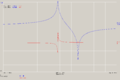
Measured course of the serial frequency (marker 1), as well as parallel frequency caused by C 0 (marker 2) and phase angle of a quartz.

View of the secondary resonances of a quartz crystal.


In the representation of the locus of the impedance of an oscillating crystal, further terms related to the properties of the oscillating crystal can be clearly explained:
The resonance frequency f r occurs when the reactance X of the resonator becomes zero. This then includes the resonance resistance R r . The anti-resonance frequency f a with the associated resistance R a is located at the high-resistance intersection of the local circle with the real axis . The extension of the vector of the series resonance frequency f s leads to the parallel resonance f p , the point at which the quotient of the square of the reactance of the parallel capacitance in the series resonant X 0 and the loss resistance R 1 (X 0 2 / R 1 ) is greatest. The frequency at which the impedance of the quartz reaches the minimum value is the minimum impedance frequency f m . The point on the local circle at which the impedance reaches its maximum value is the maximum impedance frequency f n .
The equivalent circuit of the quartz oscillator has two resonance frequencies at which the impedance is real, i.e. the phase angle is zero: the resonance frequency f r and the higher antiresonance frequency f a . Numerically, the resonance frequency corresponds to f r approximately to the series resonance frequency f s , which is the resonant frequency of the crystal is obtained from the series circuit of the dynamic components. In contrast, the anti-resonance frequency f a is often confused with the parallel resonance frequency f p . The value of the series resonance frequency f s is neglecting the loss resistance


Since the equivalent circuit of the quartz crystal also contains the static capacitance C 0 connected in parallel , the resonance, including this capacitance, can also be defined as the parallel resonance frequency f p :

The ratio of the shunt capacitance C 0 of dynamic capacitance C 1 is r mentioned:

The distance between the series and parallel resonance frequencies is:

Or simplified for large values ( r > 25):

Quality factor and bandwidth
The quality factor Q of a quartz oscillator, also called vibration quality , can be calculated from the values of the dynamic capacitance C 1 , the dynamic inductance L 1 and the dynamic loss resistance R 1 from the equivalent circuit using the following formulas , neglecting the static capacitance C 0 .

Compared to conventional LC resonance circuits, the values of the dynamic inductance L 1 are relatively high, those of the dynamic capacitance C 1 are extremely low, and the values of the dynamic loss resistances R 1 are in the range of very low two-digit ohm values. For example, the values for a commercially available quartz crystal with 10 MHz are L 1 = 25 mH, C 1 = 0.01 pF and R 1 = 65 Ω. The quality factor of 25,000, which is usual for quartz crystals and is quite high compared to LC circles, is calculated from these values.
The bandwidth B of a resonance circuit is given by the relationship

expressed. With the above 10 MHz quartz crystal with a quality factor of 25,000, the bandwidth is in the range of 400 Hz.
Applications

Oscillating crystals are mainly used in electrical engineering and communications engineering and can be manufactured over a wide frequency range. You can find z. B. in practically all transmission systems , less often in receivers , in quartz watches , as clock generators in computers and microcontrollers as well as in frequency counters and digital signal generators . Quartz crystals are also suitable for the implementation of filters .
Even as a consumer item, quartz crystals have relative error limits in the order of magnitude of 0.001%. Otherwise such small error limits can only be achieved with extreme effort or not at all in measurement technology .
- Comment:
- 0.001% = 10 ppm = 1 in 100,000 ≈ 1 second per day ≈ 30 seconds per month
- This is the usual lower limit for clocks. Adjusted clocks have lower error limits of less than 3 seconds per month.
With appropriately cut quartz crystals, very precise temperature sensors can be produced due to the temperature response of the resonance frequency .
In coating systems, freely suspended quartz crystals are used to measure the layer thickness achieved by tracking the change in their resonance frequency, which is caused by the increase in mass as a result of the layer formed on the quartz.
Although quartz crystals can be produced for any desired resonance frequencies within a permissible range through mechanical processing, some essential frequencies have been found commercially. In extracts these are:
| Frequency in MHz | Primary application |
|---|---|
| 0.032768 | Clock quartz in real-time clocks and electromechanical quartz clocks in the form of a tuning fork; allows division by 2 15 to get a second pulse. |
| 1.8432 | Clock for UARTs ; allows whole number divisions at common bit rates such as 9600 bps. |
| 3.579545 | Frequency of the color carrier in the US color television standard NTSC . Due to its widespread use, this frequency is also used for multi-frequency dialing in telephony. |
| 3.686400 | Clock for microcontroller and UART; allows whole number divisions at common bit rates such as 9600 bps. |
| 4,43361875 | Frequency of the color carrier in the color television standard PAL . |
| 10.245 | Used in older, analogue VHF radios to mix the intermediate frequency from 10.7 MHz to 455 kHz. |
| 11.0592 | Clock for microcontroller and UART; allows whole number divisions at common bit rates such as 9600. |
| 11.2896 | Digital audio systems such as the compact disc (CD), which work with a sampling rate of 44.1 kHz. |
| 12.0000 | Used with USB devices. |
| 12.288 | Digital audio systems such as digital audio tape and sound cards , which work with a sampling rate of 48 kHz. |
| 25,000 | Use with Fast Ethernet and the Media Independent Interface (MII). |
| 27,000 | The main beat for digital video devices such as DVD players . |
| 33.33 | Usual external clock for main processors before the PLL |
- Fundamental quartz: printed in kHz
- Harmonic crystal: imprint in MHz
standardization
The standardization of quartz oscillators encompasses the entire scope of the issues arising in this regard, starting with synthetic quartz crystal, the terms and applications of quartz oscillators to the measurement conditions for measuring electrical parameters.
The definitions and guidelines for the application of synthetic quartz crystals are specified in the
- DIN EN 60758, Synthetic Quartz Crystal - Specifications and guidelines for use
The basic terms and the definitions for the tests of the electrical parameters of the quartz crystal are specified in the basic specification as well as in the related general specifications:
- DIN EN 60122-1, part 1: Basic specification for quartz oscillators with assessed quality
- DIN IEC 60122-2, Part 2: Guide to the use of quartz crystals for frequency stabilization and selection
- DIN IEC 60122-2-1, Part 2: Guidelines for the use of quartz crystals for frequency stabilization and selection for clock supply of microprocessors;
- DIN EN 60122-3, Part 3: Standard housing dimensions and connection wires
The conditions for the measurement rules for the electrical parameters of the quartz crystal are specified in the following standards:
- DIN EN 60444-1, measurement of the resonance frequency and the resonance resistance of quartz oscillators using the zero-phase method in a π network
- DIN EN 60444-2, measurement of the dynamic capacity of quartz crystals using the phase offset method
- DIN EN 60444-3, measurement of the two-pole parameters of quartz crystals up to 200 MHz with compensation of the parallel capacitance Co
- DIN EN 60444-4, measurement of the load resonance frequency fL of the load resonance resistance RL and calculation of other derived values of quartz oscillators up to 30 MHz
- DIN EN 60444-5, measuring method for determining the equivalent circuit parameters of quartz oscillators with automatic network analyzer technology and error correction
- DIN EN 60444-6, measurement of load dependency (DLD)
- DIN EN 60444-7, measurement of activity and frequency dips of quartz crystals
- DIN EN 60444-8, test setup for surface-mountable quartz oscillators
- DIN EN 60444-9, measurement of the secondary resonances of quartz crystals
Further standards that deal with components that are directly or indirectly related to quartz crystals are:
- DIN EN (IEC) 60679ff. Oscillators
- DIN EN (IEC) 60368ff. Quartz filter
- DIN EN (IEC) 60862ff. & 61019ff. SAW filters & resonators
- DIN EN (IEC) 61337ff. Dielectric resonators
market
The market for quartz crystals is divided into three areas. On the one hand, there are the quartz oscillators as individual components that are installed separately by users in the corresponding circuits; on the other hand, there are the quartz oscillators, which are each provided with a quartz resonator, i.e. a quartz oscillator. The third group are the so-called "clock generators", the tuning fork crystals for clocks. It is estimated that the global demand for quartz crystals for each area in 2010 will be approximately the value of approximately 1.5 to 1.8 billion US dollars, bringing the total value worldwide to approximately 4.5 to 5.4 billion US dollars amounts.
See also
literature
- Bernd Neubig, Wolfgang Briese: The large quartz cookbook . Franzis', Feldkirchen 1997, ISBN 3-7723-5853-5 ( online ).
Web links
- Marvin E. Frerking, Fifty Years of Progress in Quartz Crystal Frequency Standards (1996)
- Warren A. Marrison, The Evolution of the Quartz Crystal Clock (1948, Engl.)
Individual evidence
- ↑ Patent US2212845 : Generating and transmitting electric currents. Registered April 10, 1918 , published August 27, 1940 , inventor: Alexander M. Nicholson.
- ^ A History of the Quartz Crystal Industry in the USA. Virgil E. Bottom, from the Proceedings of the 35th Annual Frequency Control Symposium 1981.
- ↑ The first publication on the practical structure of crystal oscillators appeared in 1924 in: HS Shaw: Oscillating Crystals. In: QST Magazine Vol. XI, No. 7, 1924 (see online ). See also PRJ Brown: The influence of amateur radio on the development of the commercial market for quartz piezoelectric resonators in the United States . In: Proceedings of the 1996 IEEE International Frequency Control Symposium, 1996. 50th . IEEE, 1996, ISBN 0-7803-3309-8 , doi : 10.1109 / FREQ.1996.559819 .
- ^ Warren A. Marrison: The Evolution of the Quartz Crystal Clock. In: The Bell System Technical Journal. Vol. XXVII, 1948, pp. 510–588 ( Reprint online ( Memento of the original of July 17, 2011 in the Internet Archive ) Info: The archive link has been inserted automatically and has not yet been checked. Please check the original and archive link according to the instructions and then remove this notice. ).
- ↑ The quartz crystal. Valvo-GmbH Hamburg, April 1964.
- ↑ a b c d e f g h Bernd Neubig, Wolfgang Briese: Das Grosse Quarzkochbuch. Franzis-Verlag, Feldkirchen 1997, ISBN 3-7723-5853-5 . Chapter 2 (PDF; 1.6 MB)
- ↑ QUARTZ CRYSTAL, THE TIMING MATERIAL, Fortiming Corporation [1]
- ↑ a b c d Bernd Neubig: Modern technologies for quartz oscillators and quartz oscillators.
- ↑ a b c W. Briese: Properties of quartz crystals
- ↑ AT cut, archived copy ( Memento of the original dated November 6, 2009 in the Internet Archive ) Info: The archive link was inserted automatically and has not yet been checked. Please check the original and archive link according to the instructions and then remove this notice.
- ↑ Representation of quartz sections Archived copy ( Memento of the original from December 4, 2010 in the Internet Archive ) Info: The archive link was inserted automatically and has not yet been checked. Please check the original and archive link according to the instructions and then remove this notice.
- ↑ Crystals and oscillators, Jerry A. Lichter ( PDF )
- ↑ Crystal Technology, 4timing.com [2]
- ^ Crystal and frequency control glossary, Icmfg.com. Archived copy ( memento of the original dated November 6, 2009 in the Internet Archive ) Info: The archive link was inserted automatically and has not yet been checked. Please check the original and archive link according to the instructions and then remove this notice.
- ^ Paul W. Kruse, David Dale Skatrud: Uncooled infrared imaging arrays and systems . Academic Press, 1997, ISBN 0-12-752155-0 , pp. 273 ( limited preview in Google Book search).
- ↑ Crystals and oscillators, Jerry A. Lichter ( PDF )
- ↑ Patent US4985687 : Low power temperature-controlled frequency-stabilized oscillator.
- ↑ Patent US4499395 : Cut angles for quartz crystal resonators.
- ↑ a b c Jerry A. Lichter: Crystals and oscillators (PDF; 176 kB).
- ↑ Patent US4419600 : Stress-compensated quartz resonators.
- ↑ a b c Patent US5686779 : High sensitivity temperature sensor and sensor array.
- ↑ Y Cut Crystal ( Memento of the original from July 30, 2012 in the web archive archive.today ) Info: The archive link was inserted automatically and has not yet been checked. Please check the original and archive link according to the instructions and then remove this notice. . Engineersedge.com (August 25, 2009).
- ↑ Info: The archive link was inserted automatically and has not yet been checked. Please check the original and archive link according to the instructions and then remove this notice. . Ieee-uffc.org (March 23, 1959).
- ↑ Glossary of terms used in the quartz oscillator-plate industry (PDF; 521 kB)
- ↑ All about Quartz Devices Archived copy ( Memento of the original from May 31, 2010 in the Internet Archive ) Info: The archive link was automatically inserted and not yet checked. Please check the original and archive link according to the instructions and then remove this notice.
- ↑ Martin Wucherer, Achim Krumrein: Quartz & Quartz Oscillators . ( Page no longer available , search in web archives ) Info: The link was automatically marked as defective. Please check the link according to the instructions and then remove this notice. (PDF; 2.0 MB)
- ^ Quartz Crystal Basics: From Raw Materials to Oscillators, Ken Hennessy, NDK America, Inc; published in High Frequency Electronics issue December 2007 Vol. 6 No. 12 ( PDF )
- ↑ a b Wintron plant tour.
- ↑ Frequency Electronics, Inc., Tutorial, Precision Frequency Generation ( PDF )
- ↑ Frank Sichla - HF technology with the NE / SA612 - beam-Verlag - ISBN 978-3-88976-054-8
- ↑ Karin Zühlke: Our goal is to make quartz obsolete. ( Page no longer available , search in web archives ) Info: The link was automatically marked as defective. Please check the link according to the instructions and then remove this notice. In: Market & Technology. No. 27, July 2, 2010. (Interview with Markus Lutz from SiTime )