
Ceramic resonator

Ceramic resonators or piezoceramic resonators are electronic components made from piezoceramics or a ferroelectric material. This difference is important because not every piezoceramic has ferroelectric properties, but every ferroelectric has piezoelectric properties. They use the piezoelectric effect for frequency- determining or frequency-selecting applications and are used in a similar way to crystal oscillators , but do not have the same frequency accuracy and stability. Compared to quartz oscillators, ceramic resonators have smaller dimensions and a lower requirement for external electronic components, are more robust with regard to mechanical loads and cost less. Simple electrical filters can also be produced by mechanically coupling two or more resonators .
functionality

If certain anisotropic crystals or ferroelectric ceramic materials are mechanically deformed, electrical charges are generated on their surface. This piezoelectric effect, the piezoelectricity, is also reversible, that is, if an electric field is applied to this material, it is deformed (inverse piezoelectric effect). As soon as the electric field is no longer present, the material takes on its original shape again, whereby an electric voltage is generated.
The mechanical deformation of the ferroelectric material of a ceramic resonator, once caused by the application of a voltage, generates an electrical signal after the voltage is switched off . By means of a feedback circuit , this signal can be used to generate a mechanical resonance vibration of the material, with a stable clock signal with a relatively precise frequency and defined amplitude .
Ceramic resonators vibrate as a thickness shear oscillator over the longitudinal axis of the ceramic. For frequencies above about 8 MHz, the 3rd harmonic of the resonance is used to clock the circuit
Construction and manufacture
Mixtures of finely ground granulates made of ferroelectric materials serve as the basis for ceramic resonators . These are often mixtures based on lead-zirconate-titanates , lead-magnesium-niobium-titanates or potassium-sodium-niobates , to which small additions of niobium , strontium , barium , lanthanum and antimony are added to modify the properties.
The production of piezoelectric ceramics can be demonstrated using the example of a lead zirconate titanate ceramic. A first thermal treatment is used to bring the starting material, a multi-phase powder mixture, into a desired chemical compound. This takes place during the reaction of the multi-phase powder mixture to lead zirconate titanate at around 800 ° C. It results from the solid phase reaction from the chemical reaction that takes place during atomic diffusion at temperatures below the melting points of the raw material components. When the raw materials decompose, gaseous by-products (e.g. CO 2 , O 2 ) are also released. The reaction during this first thermal treatment is called calcining or pre-sintering.
After calcining , the material is finely ground again. This increases the homogeneity of the ceramic. The grain size of this powder is then typically 3–6 µm. A binder then turns the powder into a plastically deformable mass that can be pressed into any shape, such as disks or cuboids and sizes. In the second heating process of production, which takes place in two subsequent heating processes, the compacts are first pre-fired at low temperatures to remove the binder, then the ceramic of the resonator cell is burned from the compacts at high temperatures in a sintering process . The ceramic is chemically inert and insensitive to moisture and other atmospheric influences.
The microstructure of the sintered ceramic produced in this way is now a polycrystalline material whose crystallites contain white areas (domains) whose elementary dipoles are aligned in parallel, but whose alignment is statistically distributed throughout the material. If this material is now exposed to mechanical stress, charge shifts take place in it as a result of the deformation, as a result of which free charges occur on the interfaces of the crystallites. Because of the statistical directional distribution of the domains, if the entire sintered body were mechanically stressed, the sum of all charge shifts would be zero. For this reason, when ceramic resonators are manufactured, the material is polarized after sintering, that is, the domains as a whole are rectified. This is done by applying a strong external constant field at temperatures that are just below the Curie temperature of about 340 ° C. This polarization also results in a (small) change in length of the sintered body. After cooling, the electrical dipoles retain their polarization direction (remanent polarization) imposed by the constant field and the material has its desired piezoelectric properties.

The individual resonator cells are then cut to the required size from the sintered and polarized ceramic and ground. The electrodes , with which the voltage generated by the oscillation of the ceramic is removed, are then metallized onto the end faces. Connection wires or connection surfaces that are electrically conductively connected to the electrodes form the contact for the subsequent circuit.
The covering of the ceramic resonator has a special feature. The sintered body must be able to vibrate mechanically freely and, if possible, without damping. For this purpose, the piezoceramic provided with electrodes and connections can first be coated with a layer of wax. A porous plastic coating is then applied to the body and cured. During subsequent heating, this sucks up the wax and the resonator can vibrate freely within its envelope.
A special feature of ceramic resonators is that two load capacitances are brought out. This is because the metallized end faces of the ceramic, with a metallization arranged centrally on the ceramic body, form two capacitors in series, the center connection of which can be led out.
Electrical behavior
Electrically, a ceramic resonator behaves like an oscillator circuit , consisting of a lossy series resonance circuit with an inductance , a capacitance , the electrical loss resistance and a (static) parallel capacitance .


Since a ceramic resonator is an oscillating mechanical system, the mechanical properties are converted into corresponding electrical values of the resonance circuit. The oscillating mass of the resonator then corresponds to the inductance , the mechanical system to the dynamic capacitance and the mechanical friction losses are represented by the ohmic resistance . The static capacity is created by the metallized electrical connections on the ceramic. It is called “load capacitance” in the data sheets and, in many resonator designs, is led to the outside with the help of a third connection in the middle and can be wired accordingly, which means that corresponding external components are not required. Resonators that are intended for use in discriminators are usually of this 3-pole design. Resonators that are intended for use in oscillators are usually 2-pole and are wired like quartz oscillators.
- Circuit diagram, equivalent circuit and basic circuit of an oscillator circuit

Circuit symbol of a ceramic resonator with a capacitive connection

Electrical equivalent circuit of a ceramic resonator

Basic circuit of a Pierce oscillator circuit with a ceramic resonator with a capacitive connection


The frequency behavior of a ceramic resonator can be shown on the impedance curve. The amount of impedance | decreases in this curve | with increasing frequency initially down to a minimum, the point of series resonance , at which the capacitive and inductive reactance cancel each other out in a series resonant circuit and only the ohmic losses are effective. As the frequency continues to rise, the impedance rises to a maximum, the point of parallel resonance, also known as the anti-resonance frequency. In the area between the two resonance points, the resonator behaves inductively, outside this area it behaves capacitively. Ceramic resonators are basically operated in the inductive range between the two resonance frequencies. The resonance is started and maintained by inverting amplifiers or inverting logic gates with an amplifier function, which generate a phase shift of 360 °.


properties
Housing and dimensions
- Types of ceramic resonators

4 MHz ceramic resonator with capacitive connection
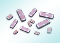
SMD ceramic resonators with capacitive connection

Design of a commercially available ceramic resonator


Ceramic resonators are supplied in many industry-standard housings, plastic-coated or ceramic-encapsulated. Naturally, the resonators for the lower frequencies in the kHz range have the largest dimensions and are usually only offered in radially wired form for circuit board assembly. For frequencies from around 2 MHz, SMD designs for surface mounting on circuit boards or substrates predominate.
A major advantage of ceramic resonators are the sometimes significantly smaller dimensions compared to quartz oscillators, because the mechanical properties of the piezoceramics enable them to achieve a desired resonance frequency even with smaller body dimensions. In addition, they can fulfill their function without bulky glass or metal housings. There are z. B. SMD ceramic resonators for 10 MHz in 0805 format (3.2 mm × 1.2 mm footprint) are offered.
A corresponding SMD quartz crystal has z. B. the dimensions 3.2 mm × 2.5 mm base area. This means that quartz oscillators require about twice as much floor space as corresponding ceramic resonators. In addition, most ceramic resonators have built-in load capacitors. As a result, the entire component outlay and thus the entire space requirement in the oscillator circuit can be reduced.
Resonance frequency
Ceramic resonators for electronic devices are manufactured for resonance frequencies from about 300 kHz up to about 70 MHz. They thus cover a very large range of working frequencies in electronics.
In addition to the standard ceramic resonators up to around 70 MHz, special manufacturing processes can also cover the much higher frequency range up to around 3 GHz.
Frequency tolerance
In oscillator circuits, it is generally customary to specify the tolerance of the resonance frequency with the quality factor or, for short, the quality Q. The quality results from the values of the inductance , the capacitance and the loss resistance of the equivalent circuit diagram.

With the help of the quality, the bandwidth at the resonance frequency can be calculated:


The bandwidth of a frequency curve is smaller, the greater the quality or the quality factor .

Example: A quartz crystal with a resonance frequency of 10 MHz is specified with a quality of 10 5 . The bandwidth is then 100 Hz. Usual frequency tolerances for ceramic resonators are between ± 0.1 and ± 0.5%. They are specified as an initial tolerance at a defined temperature and have a significantly wider bandwidth at their resonance frequency than quartz crystals. The deviation from the resonance frequency is given either in percent or in parts per million (ppm). In this specification, 0.1% then corresponds to 1000 ppm. However, the percentage is provided with the sign “±”, so that ± 0.1% results in a total width of 0.2% or 2000 ppm. In relation to the resonance frequency of 10 MHz, this means that the resonator in this example has a bandwidth of 5 kHz, which in this case corresponds to 50 times the value compared to the quartz oscillator.
The specified frequency tolerance of a ceramic resonator is a measure of the accuracy of its output frequency at a specified temperature in the delivery condition. The entire frequency tolerance is made up of the initial tolerance determined by the material properties, the temperature-dependent tolerance over the operating temperature range and the aging. The sum of all three tolerances results in the value that is decisive for the desired area of application.
With ceramic resonators that are common today, the temperature-dependent material properties result in an overall tolerance of the resonator in addition to the initial tolerance, which can reach values of around ± 9,000 ppm or more. This value, which is quite high compared to quartz crystals, is, however, suitable for many applications in electronic devices, e.g. B. in the timing of microcontrollers, still acceptable. However, more recent developments have made the frequency tolerance of ceramic resonators significantly lower. Values of ± 3000 ppm characterize this development trend and new materials with better temperature characteristics for ceramic resonators, which offer a frequency tolerance of ± 500 ppm, now even allow direct comparison with quartz crystals.
Jitter
Under jitter (engl. For "fluctuation" or "fluctuation") is meant the undesirable fluctuations of the clock signal , usually caused by thermal noise or phase noise. Jitter is normally undesirable as an interference signal. Since the frequency tolerances for quartz oscillators are normally significantly lower than for ceramic resonators, it is generally assumed that the jitter of ceramic resonators is greater than that of quartz resonators. However, comparative tests between quartz and ceramic resonators have now shown that z. B. the short-term jitter (periodic jitter) of about 10 ppm at 8 MHz between ceramic and quartz resonators is approximately the same. The long-term jitter in both resonator types has now also proven to be largely identical.
Aging
The change in the resonance frequency of ceramic resonators over time is called aging. It is based on the fact that some of the dielectric dipoles aligned in parallel in their dielectric domains decay over time due to a lack of stability. This means that they change their orientation and then no longer contribute to the piezoelectric effect. This ultimately changes the resonance frequency and the resonator "ages". The frequency change is greatest in the first hour after the ceramic has been polarized, after which it follows a logarithmic law. A few days after polarization, the measurable change in frequency over time is quite small. It is stated in the data sheets of leading manufacturers at around ± 0.3% per 10 years. However, higher temperatures above the nominal range can accelerate aging.
Coupling factor
The efficiency of the conversion of electrical into mechanical energy or vice versa in the respective piezoelectric material is indicated by the electromechanical coupling factor. This value is higher by a factor of 5 for ferroelectric ceramics than for quartz materials .
Another source puts the coupling factor of ceramic resonators as 1000 times greater than that of quartz crystals . Ceramic resonators therefore deliver a signal with a significantly higher amplitude than crystal oscillators with the same drive voltage.
Switch-on speed
Due to the high effectiveness in converting mechanical into electrical energy, the transient behavior of ceramic resonators, the so-called start-up time, is in some cases significantly faster than with quartz oscillators with correspondingly faster feedback. The start-up time is the period of time that passes after the driver voltage has been applied until the oscillation has reached 90% of its full amplitude. Ceramic resonators run up to twenty times faster than quartz resonators and can reach settling speeds down to 0.4 ms.
Protective circuit
In quartz oscillator circuits, an external resistor is often used to protect against overvoltages which could lead to a loss of the piezoelectric properties of the quartz. Since this risk does not exist with ceramic resonators, the number of components required for oscillator circuits with ceramic resonators is lower by dispensing with the protective resistor.
Areas of application
Ceramic resonators are used in a large number of electronic devices due to their low price and their small dimensions. They are used, for example, as clock generators in microprocessor circuits in which the frequency accuracy is not critical. They can also be found in intermediate frequency filters in radio receivers, as clocks or signal generators in inexpensive clock circuits, televisions , video recorders , household appliances, cell phones , copiers , digital cameras , voice generators , remote controls and in toys.
More recent developments in the field of ceramic resonators have a significantly better frequency accuracy and lower temperature dependency, so that they can also be used in typical areas of application of frequency-stable crystal oscillators, for example in USB interfaces or in local networks in vehicle electronics. These new developments are based on improvements in processing methods and new materials and make it possible to offer SMD ceramic resonators in 0805 format (3.2 mm × 1.2 mm) in about half the size of corresponding quartz components.
Individual evidence
- ↑ Piezocide converter, Valvo brochure, 1968
- ↑ a b Ceramic Resonators (PDF; 714 kB). Abracon Application Notes. 2009, accessed July 28, 2010.
- ↑ TECHNICAL NOTE # 1: Piezoceramic, Integrity Technology, [1] (PDF; 31 kB). Retrieved on February 7, 2016.
- ↑ Helke, Günter: Piezoelectric ceramics, physical properties, composition, manufacturing process, parameters and practical applications
- ↑ J. Koch: VALVO Piezoxide (PXE), properties and applications. Hüthig Verlag, 1988, ISBN 3-7785-1755-4 .
- ↑ Phil Elliott, AVX, TECHNICAL INFORMATION, SURFACE MOUNT CERAMIC RESONATORS, PDF
- ↑ Ceramic resonator principles, ECS, PDF
- ↑ Murata, Ceramic Resonators (CERALOCKr) (CSTCE_G_A, 8.00-13.99 MHz) PDF; 1.2 MB . (Accessed February 14, 2018)
- ↑ Petermann-Technik GmbH, MINI-SMD-CRYSTAL SERIES SMD03025 / 4 Archived copy ( memento of the original from February 14, 2016 in the Internet Archive ) Info: The archive link was automatically inserted and not yet checked. Please check the original and archive link according to the instructions and then remove this notice. (accessed on February 7, 2016)
- ↑ Murata, Ceramic Resonators Ceramic Resonators (CERALOCK) [2]
- ↑ Ulrich L. Rohde: Ceramic Resonator Oscillators Challenge SAW Performance, Microwaves & RF, September 2003, [3] (accessed on February 14, 2016; ED Online ID # 5895).
- ↑ a b c d e Kazutaka Hori, Murata, elektroniknet.de, April 17, 2008, ceramic resonators vs. Crystal oscillators ( Memento of the original from November 19, 2011 in the Internet Archive ) Info: The archive link was automatically inserted and not yet checked. Please check the original and archive link according to the instructions and then remove this notice. and [4] (accessed February 14, 2016)
- ↑ Piezoceramic resonator. In: Dieter Sautter, Hans Weinerth: Lexicon Electronics and Microelectronics. VDI-Verlag, 1990, ISBN 3-18-400896-7 , p. 507 ( limited preview in the Google book search).
- ↑ 8-Pin FLASH-Based 8-Bit CMOS Microcontrollers, PIC12F629 / 675 Data Sheet, (PDF; 5.0 MB) (accessed February 14, 2016)