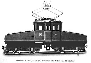
Saxon I ME
| KSStE I ME 1 and 2 DR E 191 01 and E 191 02 |
|
|---|---|
|
Factory photo of machine number 1, still without the surrounding paneling of the bogies and without the direction indicators that were retrofitted later
|
|
| Numbering: | I ME 1-2 E 191 01-02 |
| Number: | 2 |
| Manufacturer: |
Saxon machine factory (mech.) Siemens-Schuckert (electr.) |
| Year of construction (s): | 1914 |
| Retirement: | 1967 |
| Axis formula : | B'B ' |
| Gauge : | 1000 mm ( meter gauge ) |
| Length over buffers: | 9,275 mm |
| Length: | 8,110 mm |
| Height: | 3,300 mm |
| Trunnion Distance: | 4,700 mm |
| Bogie axle base: | 1,500 mm |
| Total wheelbase: | 6,200 mm |
| Service mass: | 30.0 t |
| Top speed: | 20 km / h |
| Hourly output : | 150 kW |
| Continuous output : | 130 kW |
| Starting tractive effort: | 6,129 kp |
| Performance indicator: | 5.0 kW / t |
| Driving wheel diameter: | 1,000 mm |
| Power system : | 650 V = |
| Power transmission: | Overhead line |
| Number of traction motors: | 2 |
| Drive: | Pawbearing / rod drive |
| Brake: | Westinghouse air brake |
As Genus I ME designated Royal Saxon State Railways the electrical freight - locomotives of the narrow-gauge railway Klingenthal Sachsenbergstraße-George Thal . In popular parlance , the two locomotives were referred to as lattice trumpets ("Güterrumpel") because of their running noise and their use in front of freight trains .
history
The two locomotives were procured for the route from Klingenthal to Sachsenberg-Georgenthal , which was the only Saxon narrow-gauge railway to be electrified because of its tram-like operation . The electrical equipment was supplied by the Siemens-Schuckert works in Berlin , while the mechanical part was built by the Sächsische Maschinenfabrik in Chemnitz. Shortly before the outbreak of the First World War , the two locomotives were delivered to the Royal Saxon State Railways in July 1914 with the serial numbers 3759 and 3760 and the company numbers 1 and 2.
Initially, the locomotives in Klingenthal were parked unused because the beginning of the war interrupted the construction work on the line. The electrical systems in Klingenthal were not completed until almost three years later, so that the locomotives were first used in front of freight trains on April 20, 1917.
The Deutsche Reichsbahn , founded in 1920, initially continued to use the two locomotives under their old generic name. It was not until 1939 that they were given the new numbers E 191 01 and E 191 02; according to another source, they were not changed until 1948.
The two locomotives handled all goods traffic on the narrow-gauge railway until it was discontinued on April 9, 1963. Operations in passenger train traffic took place only in exceptional cases, for example when the railcars failed.
After the final shutdown of the railway in April 1964, the locomotives were initially parked unused in Klingenthal. In 1967, after several unsuccessful sales attempts, the locomotives were finally transferred to the State Railroad Repair Shop in Dessau , which was responsible for maintenance from 1935 , and scrapped there.
technical features
- Mechanical part
The locomotives had a riveted bridge frame made of sectional steel. The driver's cab was arranged in the middle between two porches in which the electrical equipment was located.
The bogies had external frames; each inner axle was driven. The power transmission to the second axle in the bogie took place via Hall cranks and coupling rods. In order to avoid accidents in road traffic, the bogies were subsequently given an all-round cladding into which the two snow clearers were integrated.
As a pulling and pushing device, the locomotives had the funnel coupling common on the Saxon narrow-gauge railways with coupling heads of different lengths.
The locomotives had a Westinghouse brake with an additional brake as braking equipment . The air compressor and main air tank were located in the front end, the auxiliary air tank was attached to the outside of the frame.
- Electrical part
The pantograph and main switch were located on the roof of the driver's cab . The pantograph initially had three, later only two contact strips. It was applied with spring force. A spark gap served as a surge arrester .
The drive switch had two switch-on rollers connected in parallel so that both drive motors could also be operated individually. As at that time usual for DC vehicles carried the power adjustment via a series - parallel with Anfahrwiderständen. There were two continuous driving levels.
The two traction motors were designed as direct current series motors in a pin bearing arrangement. They were self-ventilated.
literature
- Rainer Heinrich: The Klingenthal narrow-gauge railway and the history of the Klingenthal standard-gauge station . 2nd Edition. Kenning Verlag, Nordhorn 2000, ISBN 3-933613-27-2 .
- Fritz Näbrich, Günter Meyer, Reiner Preuß: Lokomotivarchiv Sachsen 2 . 1st edition. transpress Verlag, Berlin 1984.
- Erich Preuss, Reiner Preuss: Narrow gauge railways in Saxony . 1st edition. transpress Verlag, Stuttgart 1998, ISBN 3-613-71079-X .
