Buoyancy aid

A lift aid is a device on the wings of an aircraft which is used to increase the lift coefficient in certain flight situations . The use of buoyancy aids makes aircraft airworthy even at lower speeds, which in particular simplifies take-off and landing ; They also cause an increase in air resistance , as is often required during the landing phase.
history

The difference between cruise speed and take-off or landing speed was small in early civil aviation, so that no lifting aids were necessary. Nevertheless, simple flap systems were designed, for example to improve visibility when landing, or to better control the glide path.
With the development of faster aircraft, problems arose during takeoff and landing. The wings with high wing loading, designed as swept wings for high cruising speeds, did not generate enough lift at low speeds, so that extremely high take-off and landing speeds and long taxiways would have been necessary. To compensate for the large differences in lift, buoyancy aids were introduced for the slow flight phases.
commitment

The first aircraft to have high-lift aids over the entire span, both on the leading edge of the wing and on the trailing edge, was the Fieseler Storch . Buoyancy aids are used in particular during take-off and landing , and more rarely when climbing and when maneuvering an aircraft. Only in rare cases (see Douglas DC-8 ) are they also used during cruising. The aim of using buoyancy aids is to increase lift, especially during take-off, in order to shorten the required runway length. Disadvantages are a reduced climbing angle, as the air resistance is slightly increased. During the landing phase, buoyancy aids are used in descent to reduce the landing speed, to reduce the required runway length and to considerably increase the air resistance to achieve the necessary glide angle. High-lift aids enable STOL aircraft to take off and land over very short distances.
The permissible speed range with the flaps extended is marked on the airspeed indicator with a white arc.
Types of buoyancy aids
Buoyancy aids differ in their structure and position on the wing. Lifting aids act either on the wing curvature , the wing surface , on the boundary layer of the air flow around a wing or by deflecting the engine jet.
A basic distinction is made between two types of buoyancy aids:
- Wing trailing edge flaps
- Wing leading edge flaps
Buoyancy aids on the wing leading edge
Kruger flap
The Krueger flap is a relatively simple device that changes both the wing curvature and the wing area, so that the stall speed is reduced and at the same time the maximum lift coefficient is increased. A distinction is made between a simple Kruger flap and a Kruger flap with a gap (Vented Kruger Flap).
Slat
The leading edge slat (engl. Slat ) is an extendable or rigid lower wing, which is located at the leading edge of the airfoil. Air can flow from the underside to the upper side of the wing through the gap between the fore and main wing, preventing a stall at high angles of attack . If it is designed to be movable, the effective wing area increases at the same time.
Some aircraft have slats which, due to the aerodynamic forces acting on them, extend and retract automatically as the situation requires (e.g. Messerschmitt Bf 108 or Morane MS 880 Rallye ). There are two types of slats. The first is a slat with a gap (Slat) and the second type is a slat without a gap (sealed Slat)
Tilted nose
When Kippnase (Engl. Droop Leading Edge Flap or droop nose) is the complete wing leading edge angled downward. This increases the wing curvature, e.g. B. Northrop F-5 .
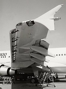
On the Airbus A380 , this approach was implemented as a so-called droop-nose device on the inner wing, while the outer wing was equipped with conventional slats.
Buoyancy aids on the trailing edge of the wing
These buoyancy aids are colloquially known as landing flaps , although they are also used during take-off. In technical terms, they are simply called flaps ( flap , plural flaps ).
Flap
A flaperon (engl. Plain flap) is the simplest form of the lift aid: The rear end of the support surface is designed to pivot. Flaps are usually extended at the same angle on both wings. However, when they are coupled to the aileron (English aileron ), one speaks of the flaperon , as used in the F-16 Fighting Falcon . On some aircraft, when the flaps are extended, the ailerons are also lowered in the same direction (e.g. Dornier Do 27 , Messerschmitt Bf 109 E or McDonnell Douglas F / A-18 ).
In gliders , the gliding performance is optimized by the position of the flaps between the positive landing position and the negative high-speed flight position. The ailerons can be coupled to the flaps; in this case they are included in the bulge. By increasing the curvature, the lift, but also the drag are increased. During high-speed flight, the curvature is reduced to zero degrees, possibly even to a negative position (−8 °), thus reducing the resistance. As a landing aid, the flap is extended steeply (up to 90 °) downwards. This results in a higher lift and, due to the enlarged blow-in area, a strong increase in drag, the gliding flight becomes steep. Open and racing class gliders usually have ailerons and flaps that span the entire span. The joystick movements for control commands around the longitudinal axis (rollers) are mixed with the lever for the flap position using mechanical mixers. A special form of this is the "butterfly" position, in which the flaps deflect positive and the ailerons negative (upwards) (example Schleicher ASW 20 ). This creates maximum resistance with full controllability around the longitudinal axis, which enables relatively steep landing approaches.
On aerobatic planes, the flaps can be opened in opposite directions with the elevator (e.g. the counter flaps of the Hirth Acrostar ).
Split flap
The slotted flap (engl. Slotted flap) as the flaps folded down. At the same time, however, this movement releases an air gap that allows air to flow onto the top of the wing and thus prevents a stall . Slotted flaps can be constructed in such a way that they open up to three gaps.
Fowler flap
The Fowler flap is a flap that is moved back and turned on below the trailing edge of the wing. As with the split flap, this frees an air gap between the top of the wing and the underside; in addition to the arching of the wing, the wing area is also enlarged.
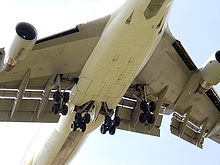
As so-called Einspaltklappe they are, for example, on all Airbus - aircraft (except for the A321 and new A400M ), as well as the A380 represented. The A321 has a double-slit high-lift system. Fowler flaps have also been designed in such a way that they release up to three gaps (also known as a Fowler system). They are used, for example, on the Boeing models B727 , B737 and B747 as well as the Tupolew Tu-154B .
Expansion flap
In the split flap (English Split flap ) is a part of the rear wing lower part is folded down. Examples: Focke-Wulf Fw 190 , Supermarine Spitfire , Mitsubishi A6M . The expanding flap is a special form of the flap that is basically reserved for powered flight only. The top of the profile remains unchanged when you press it.
Flap
The flap is an expanding flap, the front edge of which is moved backwards when it is deflected . It is used on the Lockheed C-130, for example.
Junkers double wing
In the Junkers double wing , the flap is designed as a separate small wing behind the actual wing. Junkers double wings can not only be used as lift aids, but also as control surfaces (ailerons) (e.g. Junkers Ju 52 / 3m ). Since they also have an air gap in the flight position due to their design, they increase the air resistance of the entire structure on the one hand, but on the other hand improve the slow flight behavior.
Engine-based high-lift systems
By influencing the boundary layer on a wing, the tear-off speed can be reduced and the maximum angle of attack can be increased. Either part of the air flow on the wing surface is extracted or air is blown onto the upper side of the wing by a blower. With suction, unstable speed profiles can be stabilized and thus the risk of peeling phenomena can be reduced. For this purpose, the boundary layer is sucked off in front of the separation point, so that a new, more energetic boundary layer can form. The disadvantage here is the increase in frictional resistance. Energy is supplied to the boundary layer by blowing out. The higher-energy boundary layer at the leading edge, for example, allows higher angles of attack to be flown. When blowing out at the rear edge, the risk of peeling is reduced, it works like a rear edge flap.
Control and drive
Lifting aids on the leading edge of the wing work partly automatically depending on the angle of attack and the flight speed. Other buoyancy aids are specifically used by the pilot or the fly-by-wire control or are an essential part of the landing procedure. The landing flaps are driven manually, hydraulically, pneumatically or electrically.
Above a certain speed, landing flaps can typically no longer be extended because the power of the actuator is insufficient to overcome the aerodynamic forces. At even higher speeds, which also depend on the current extension angle of the landing flaps, the flaps can even be damaged. Some aircraft therefore have landing flaps that are automatically retracted by aerodynamic forces with increasing speed (e.g. Grumman F4F ).
Angle of attack and center of lift
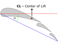
With the flaps extended, the angle of attack α (Angle of Attack, AoA) of the wing increases compared to the retracted state (flaps up). Together with the increased wing chord, this results in a significant increase in lift.
The center of lift (center of lift) shifts with flaps extended to the rear. This makes the aircraft top-heavy and therefore has to be trimmed (on many aircraft) (tail-heavy trim).
Buoyancy and drag
When the flaps are gradually extended, the lift and drag of the wing increase. However, this does not happen linearly for both values. While with the flaps slightly extended (the first flap positions, the first 50% when extending) the aerodynamic lift increases and the air resistance increases only minimally, with the flaps that are very extended (the last flap positions, the last 50% when extending) the lift only increases still minimally, while the air resistance increases very strongly.
For this reason, the flaps are only slightly extended for the take-off and approach to increase lift, while the flaps are fully extended for the final approach to greatly increase air resistance. Landing with the flaps fully extended enables a steeper approach, a faster reduction in airspeed (a large aircraft with a few hundred tons of inertial mass only reduces the airspeed very slowly) and a shorter coasting distance.
See also
- STOL
- Adaptive wing
- Alula - buoyancy aid in birds
literature
- Wilfried Copenhagen (ed.): Lexicon of aviation. Transpress, Berlin / Motorbuch Stuttgart 1991, ISBN 3-344-70711-6
- Ernst Götsch: Aircraft technology. Motorbuch, Stuttgart 2003, ISBN 3-613-02006-8 .
- The glider pilot. Volume 7, Schiffmann, Bergisch Gladbach 1997, ISBN 3-921270-18-9 .


