Eddy current brake
An eddy current brake (also induction brake ) is a wear-free brake that uses the eddy currents caused by magnetic fields in moving metal disks ( rotors ) or swords for braking.
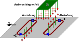
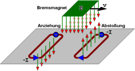
The principle: If an electrical conductor moves in a magnetic field transversely to the field lines, then voltages and consequently eddy currents are induced in the conductor , which in turn generate their own induction voltages opposite the external magnetic field according to Lenz's rule and thus in turn their own magnetic field. which ultimately slows down the movement of the conductor material ( Lorentz force ). The same applies if, conversely, the source of the external magnetic field, e.g. B. a permanent magnet or electromagnet, via an electrically conductive surface, e.g. B. a railroad track is moved - the only decisive factor is the relative movement between the field and the electrical conductor (see Fig.).
The electrical resistance of the metal plate forms an ohmic consumer for the eddy currents , which converts the kinetic energy of the conductor or the magnet into heat. The magnetizability of the metal piece, on the other hand, which plays a role in the similarly functioning hysteresis brakes, is irrelevant for the induction in an eddy current brake, only the electrical conductivity is decisive .
The idea of the eddy current brake was patented in 1892 .
control
The strength of the braking effect depends on several parameters:
- Conductivity of the brake disc
- The induced currents are directly proportional to the electrical conductivity of the material used. A copper disk is therefore braked more strongly than an identical steel disk.
- Direction of the magnetic field
- The greatest braking effect is achieved when the magnetic field penetrates the moving disc vertically.
- Air gap
- The larger the air gap, the smaller the maximum braking effect.
- Shape of the disc
- Discs with a circumferentially comb-shaped structure or cracks have a reduced braking effect, since the annular eddy currents can no longer develop over a large area.
- Area under the exciter pole
- The smaller the area under the pole, the lower the braking effect.
- speed
- The braking effect is strongly dependent on the relative speed between the field and the disk.
- Coil current
- The higher the current flowing through the magnet, the stronger the magnetic field and thus the braking force.
If a rotating disk is braked by a static magnetic field (e.g. permanent magnet ), the disk becomes slower and slower. However - because of the decrease in the braking force with the relative speed - the standstill is theoretically never completely reached. An eddy current brake is therefore not suitable as a parking brake .
Conversely, this effect offers a natural ABS . This characteristic can be influenced by a variable magnetic field, then even movement can be generated, such as B. in asynchronous motors with squirrel cage rotors or in electricity meters based on the Ferraris principle .
Creation of eddy currents
 |
A non-magnetic, electrically conductive metal plate is moved from right to left (in this example o. B. d. A. ) in a local magnetic field directed to the rear (e.g. permanent magnet). This movement and the direction of the magnetic field result in an upward force that acts on the electrons, which are still evenly distributed in the plate. |
 |
This so-called Lorentz force , however, now acts more strongly on the electrons that are closer to the magnet than on those that are further away from it. This creates a strong upward flow of electrons on the side facing the magnet. |
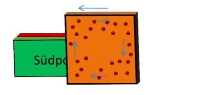 |
In order to compensate for the resulting difference in charge in the copper plate, the electrons flow downwards on the right side of the plate, since the Lorentz force is lower here than on the left. This creates a swirling clockwise electron movement. |
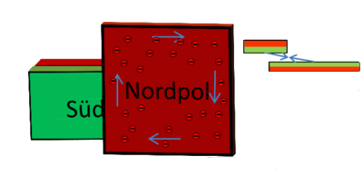 |
This electron movement in turn generates a magnetic field in the copper plate that counteracts that of the permanent magnet. The repulsion of these magnetic fields also counteracts the direction of movement of the copper plate and thus slows it down. |
 |
If the plate is now exactly in front of the magnet (in a homogeneous magnetic field), the Lorentz force acts on the electrons in the right half of the plate just as strongly as on those in the left half of the plate. Eddy currents no longer arise. |
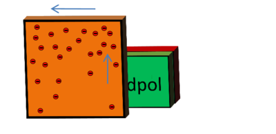 |
When exiting the magnetic field again, exactly the opposite happens: Because the right side is more penetrated by the field of the magnet than the left side, the Lorentz force also acts more strongly on the electrons here. The electrons flow upwards and create a charge difference. |
 |
This creates a vortex again, but now anti-clockwise, which creates a magnetic field that is in the same direction as that of the permanent magnet. This magnetic attraction now counteracts the direction of movement of the copper plate. |
The movement of the metal plate is decelerated both when it enters and when it exits the magnetic field. The kinetic energy is converted into thermal energy according to Ohm's law (the copper plate heats up).
Applications


Rail vehicles
The linear eddy current brake was first used in series production in Europe on the ICE 3 multiple units that went into service in 2000 . In contrast to the magnetic rail brakes that are otherwise common on fast moving trains , the magnetic field is generated along and not across the rail. The iron core of the electromagnet does not touch down, but is held about 7 mm above the upper edge of the rail by fastening it to the vehicle's axle box. With eddy current brakes, the braking energy to be dissipated is converted into heat in the rails. The problem here is the skin effect , which, due to the high frequencies, forces the eddy current to the outer edges of the rail cross-section. This is said to have caused the rail surface to anneal during the development period. The sub-components of the eddy current brake are not subject to wear and tear and work independently of the coefficient of friction between the wheel and the rail (e.g. leaves on the rail).
Eddy current brakes are used on the ICE 3 especially at high speeds. In interaction with the regenerative brake , the braking power of which is greatest at low speeds and decreases at higher speeds, operational braking delays required for operation are achieved without wear. They are integrated into a brake management system. The eddy current brake is switched off at speeds below 50 km / h, as otherwise the tightening forces would be too high and their actual effect would no longer be achievable.
In order to be able to use eddy current brakes, the track switching devices on routes used must be specially upgraded, in particular to avoid disruptions in the safety technology . In full, d. H. Also for service braking , the eddy current brake of the ICE is only used in Germany on the high-speed lines Cologne – Rhein / Main , Nuremberg – Ingolstadt and VDE 8.1 / 8.2 , as only the use of the slab track can provide sufficient positional stability against heat-related warping of the track Extreme conditions (including high outside temperature with solar radiation, dense ICE 3 train sequence) can be ensured. It is released as a service brake by LZB (with CIR-ELKE II) or ETCS Level 2 in suitable areas.
On large parts of the network used by the ICE 3, however, the eddy current brake may only be used for rapid braking . It can be counted towards the braking hundredths of the train and allows (under PZB ) a speed of 160 km / h. On the high-speed routes, some of which are approved for over 250 km / h, such as Mannheim – Stuttgart and Hanover – Würzburg , in which the eddy current brake may also only be used for rapid braking, the permissible speed of the ICE 3 is limited to 250 km / h in order to use the alternative Disc brake not to be thermally overloaded. On individual routes that are not qualified for the use of the eddy current brake for rapid braking, it is not counted towards the braking hundredths of the train, which means that the maximum speed (under PZB) is limited to 140 km / h. The use of the eddy current brake for rapid braking is stopped by the driver when the vehicle is stationary.
Before it was used in the ICE 3 passenger trains, the eddy current brake system on the ICE V and ICE S test vehicles was made ready for series production . The eddy current brake of the ICE 3 was tested as a service and high-speed brake under LZB guidance from July 2001 on the Rhine Valley Railway between Baden-Baden and Offenburg , later as part of the commissioning of the high-speed line Cologne-Rhine / Main . In the same year, a single ICE-3 train ran between Munich and Hamburg, in which the eddy current brake was switched on for service braking in the higher speed range. Eddy current brakes are installed on half of the train's wheelsets. Its braking power exceeds that of the electromotive brake in the upper speed range. Above 180 km / h the braking force is around 150 kN.
The eddy current brake of the InterCityExperimental was not initially carried over to the later ICE series trains due to problems with the infrastructure. The next generation of Siemens Velaro trains ( Velaro Novo ) will no longer have an eddy current brake.
The Shinkansen prototype Alfa-X is to be equipped with eddy current brakes for rapid braking in the event of an earthquake.
With the rotating eddy current brake , the rail is used as a magnetic core and currents are induced in the wheels of the train, whose magnetic fields interact with those of the electromagnets and thus brake the vehicle. This brake is currently only used in test vehicles.
Performance brake
The eddy current brake is used as a performance brake on engine test stands . It is used to brake a test item ( combustion engine , electric motor ). The advantages of good controllability, size and use as a system for power measurement are countered by the disadvantages of power dissipation in the form of heat and the passive mode of operation (test item cannot be towed).
Fitness equipment
In training equipment, especially in high-quality ergometers , the load is controlled by electrically adjustable eddy current brakes. By using microprocessors, these can be controlled in a variety of ways according to various parameters.
Rides
Linear eddy current brakes are increasingly being used in the ever faster and higher roller coasters and free-fall towers . Above all, the braking effect, which is more gentle in comparison to the classic block brakes based on the effect of friction , the freedom from wear and the safety of these braking systems, led to this trend. Eddy current brakes with permanent magnets do not require electricity. That is why they work perfectly even in the event of a power failure.
Depending on the type of rollercoaster car, the metal swords (mostly copper alloys) are mounted on the side or below the car. At the braking points, the blades move between permanent magnets mounted on the track. Some of the magnets can be folded away after braking to enable the train to continue its journey more easily.
If very high speeds are reached and many or long brakes are used as a result, the magnets are often mounted on the roller coaster car and the metal swords on the rail. The reason is that magnets are significantly more expensive to buy than brake blades and so fewer of them are needed. This combination is mainly found in launch roller coasters , some of which travel at speeds of over 200 km / h and where conventional friction brakes would show excessive wear. Brake swords are also installed on the acceleration section of such railways, which, in the event of a faulty launch, brake the train as it rolls back if it does not pass the following hill. The brake blades are then lowered or folded down during the acceleration phase and only brought back into the braking position after the train has passed. Lowerable brake blades are particularly characteristic of "Accelerator Coaster" from Intamin . Launching roller coasters, which are accelerated by means of a linear motor and require the magnets on the car, also have this combination.
In free-fall towers, the swords are mounted vertically on the tower and the magnets are attached to the passenger carrier. The swords are usually mounted in such a way that there are initially a few swords on the way of the gondola and more swords downwards in order to achieve an approximately constant increasing braking force.
commercial vehicles
The advantage of the wear-free permanent brake is also used in the commercial vehicle sector for trucks. The best-known manufacturers are Voith , Telma and Knorr-Bremse . As an alternative to eddy current brakes, retarders that work hydraulically are also installed. Some manufacturers try to combine the alternator , starter and eddy current brake in one unit.
Measuring device
In a moving-coil measuring mechanism , the moving coil - which moves in a permanent magnetic field - is wound onto an aluminum frame. Eddy currents therefore arise in this during pointer movements, which dampens jerky pointer movements.
In the Ferraris meter (for electrical energy), fixed current and voltage coils generate an eddy current that sets a rotating aluminum disc in motion. The disk also passes through the magnetic field of a strong permanent magnet that excites eddy currents in it. The interaction of the braking and the driving forces causes a uniform rotary movement of the disc that is proportional to the measured value (active electrical power).
literature
- Stefan Dörsch, Silvia Eickstädt, Christiane Nowak: Use of the linear eddy current brake in high-speed vehicles of the DB AG - experiences and perspectives . In: Zevrail , Volume 133, Issue 10, October 2009, p. 405 ff.
Web links
- SO Siems: LWSB - Linear Eddy Current Brake. In: TU Braunschweig - Institute for Electrical Machines, Drives and Railways, 1997 Annual Report ( Memento from August 22, 2007 in the Internet Archive )
- Video: eddy current brake . Institute for Scientific Film (IWF) 2004, made available by the Technical Information Library (TIB), doi : 10.3203 / IWF / C-14871 .
- Roller coaster brakes - from friction to eddy current brakes. Internet magazine Coasters and more
- Eddy current brake. The principle of operation. Explanation of the origin of eddy currents on ModellAchterbahn.de
Individual evidence
- ↑ a b c Peter Schmied 34th conference “Modern Rail Vehicles” in Graz . In: Eisenbahn-Revue International , Issue 12/2002, ISSN 1421-2811 , pp. 558-560.
- ↑ a b Wolf-Dieter Meier-Credner: The linear eddy current brake - development and use in the ICE 3 . In: Railway technical review . tape 49 , no. 6 , June 2000, p. 412-418 .
- ↑ a b Helmut Lehmann: Driving dynamics of the train journey . 3. Edition. Frankfurt am Main 2012, ISBN 978-3-8440-1259-0 , pp. 142, 149-151 .
- ↑ Jürgen Janicki, Horst Reinhard, Michael Rüffer: Rail Vehicle Technology . 3. Edition. Bahn-Fachverlag, Bahn Fachverlag 2013, ISBN 978-3-943214-07-9 , p. 359 f .
- ^ Holger Schülke, Herbert Weishaar, Ottmar Grein: Project PXN for the commissioning of the new Cologne – Rhein / Main line . In: Railway technical review . 50, No. 12, 2001, pp. 736-747.
- ↑ Klaus Heckemanns, Jürgen Prem, Stefan Reinicke: Brake management of the ICE® trains . In: Railway technical review . tape 53 , no. 4 , 2004, ISSN 0013-2845 , p. 187-197 .
- ↑ Heinz Kurz: InterCityExpress - The development of high-speed traffic in Germany . EK-Verlag, Freiburg, 2009, ISBN 978-3-88255-228-7 , p. 196.
- ↑ Fumio Kurosaki: Alfa-X starts three-year test programs . In: Railway Gazette International . tape 175 , no. 7 , 2019, ISSN 0373-5346 , p. 30-32 .
