Voltage doubler
A voltage doubler is a voltage multiplier and is thus a form of charge pump . Charge pumps work with the help of capacitors and diodes . From an alternating voltage supplied, they generate a direct voltage that is higher in magnitude than can be achieved with a rectifier . The specialty of a voltage doubler compared to other voltage multipliers is that there are extended circuit options for this.
General function
In contrast to charge pumps, which are supplied with direct voltage and are counted among the direct voltage converters ( English DC-DC converters ), voltage doublers do not have an oscillator due to the alternating voltage supply . As a rule, potential-controlled switches such as diodes are used as switches .
As with any charge pump, certain capacitors are initially charged during the first half cycle of the AC voltage and connected in series in the second half cycle due to the changed polarity of the input voltage, which results in a higher output voltage. If the structure of voltage doubling elements is cascaded , very high DC voltages can be generated. These circuits are called a high voltage cascade . The amount of the generated direct voltage is always above the peak value of the supplied alternating voltage.
advantages
The advantage of voltage doubling instead of using a transformer with a correspondingly high number of turns ratio and subsequent rectification consists in the following points:
- A transformer for galvanic isolation is often used as a voltage source on the input side. This does not have to be designed for the high output voltage with the insulation, the winding structure and in production.
- In the case of rectifiers in cascaded design, the high output voltage is distributed over several diodes, which means that they have to have a lower reverse voltage than a rectifier for a directly highly transformed AC voltage.
- Under certain conditions, the rectifier cascade is lighter than a transformer
- With multi-level cascading, all partial voltages can basically be tapped
disadvantage
- There is no galvanic separation between input and output
- If electrolytic capacitors are used, they can lose capacity after decades or cause a short circuit, as described in the article on electrolytic capacitors.
Types
Some of the most important voltage multipliers are shown below.
Villard circuit

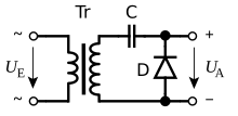
The Villard circuit represents a basic circuit and consists of a capacitor C and a diode D, as shown in the adjacent circuit diagram. Functionally, the transformer is not absolutely necessary: It is used for galvanic isolation and to raise the AC input voltage to a correspondingly high AC voltage for supplying the Villard circuit.
The Villard circuit is a clamping circuit with peak clamping : After a few periods , the capacitor is charged to the peak value of the alternating voltage supplied by the transformer on the secondary side. The voltage supplied by the transformer is shown in the voltage diagram on the left. After a few periods, the output voltage U a swings between 0 V and twice the value of the secondary-side alternating voltage, as shown on the right in the time diagram on the right.
By reversing the polarity of diode D , a negative output voltage can be achieved. In most microwave ovens , this circuit is used to generate the negative high voltage for the cathode of the magnetron . A diode cascade is used as the diode, the forward voltage is then in the range of 6 V.
Greinacher circuit
The Greinacher circuit is a further development that extends the output-side peak voltage of the Villard circuit by an additional diode D 2 and a storage capacitor C 2 and thus supplies a direct voltage with a comparatively low ripple current . The output voltage in the unloaded case is:
with as the secondary-side peak value voltage of the transformer Tr and U D as the forward voltage of the two diodes, which in silicon diodes is approximately 0.7 V per diode.
The circuit was developed by Heinrich Greinacher in Zurich in 1913 and published in 1914. To operate his ionometer , he needed a direct voltage of 200 V to 300 V, for which the alternating voltage of 110 V available in Zurich at the time was too low.
The further development in the form of a cascade is referred to as a high-voltage cascade or sometimes also as a Villard circuit. She finds z. B. in the high voltage part of tube televisions , ion implanters or in particle accelerators such as the Cockcroft-Walton accelerator application. For this accelerator, John Cockcroft and Ernest Walton developed this circuit independently from Greinacher in 1932.
Except for the input capacitor, all components must be designed for twice the peak voltage value of the supply voltage.
Delon circuit

The simple Delon circuit is also a voltage doubler and is one of the bridge circuits . The positive half-wave charges the capacitor C 1 to the peak value of the secondary-side alternating voltage via the diode D 1 , while the diode D 2 blocks. The negative half wave charges via the diode D 2 to the capacitor C 2 to the peak value of the secondary-side AC voltage. The output voltage is the sum of the DC voltages on the two capacitors with the value:
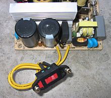
The Delon circuit is of particular importance for electrical devices which are to be operated on both the usual mains voltages in America with 110 V and in the electricity networks in Europe with 230 V and do not have a wide-range input. In this case, the bridge rectifier on the primary side is extended by the Delon circuit: When operating with 230 V, the Delon circuit is deactivated and only the bridge rectifier is active, which supplies a DC output voltage of approx. 325 V. When operating on 110 V, a switch connects the intermediate tap between the capacitors to one of the AC voltage inputs. Due to the doubling of the voltage, an equally high DC voltage of 315 V is applied to the series circuit. Primary switching power supplies connected to it can always be operated with input voltages of approx. 315 V, regardless of the various mains voltages.
The Delon circuit can also be used for quadrupling. This allows the output voltage to reach the value
increase.
Individual evidence
- ^ Ralf Kories, Heinz Schmidt-Walter: Taschenbuch der Elektrotechnik . 6th edition. Harri Deutsch, 2004, ISBN 3-8171-1734-5 (Chapter 10.2.2).
- ^ Maciej A. Noras: Voltage level shifting , Trek Application Note Number 6001, 2004, online (PDF; 452 kB).
- ↑ Heinrich Greinacher: The Ionometer and Its Application to the Measurement of radium and X-Rays , Physical Magazine, Issue 15, 1914, pages 410-415.
- Jump up ↑ Jagdish Mehra, Helmut Rechenberg: The Historical Development of Quantum Theory: Schrödinger in Vienna and Zurich 1887-1925: Part 1 . Springer, 2001, ISBN 978-0-387-95179-9 , pp. 284 .
- ↑ Ulrich Tietze, Christoph Schenk: Semiconductor circuit technology . 1st edition. Springer, 1969, p. 13 (title no.1565).
See also
literature
- Ralf Kories, Heinz Schmidt-Walter: Pocket book of electrical engineering . 6th edition. Harri Deutsch, 2004, ISBN 3-8171-1734-5 .
- Manfred Seifart: Analog circuits . 3. Edition. VEB Verlag Technik Berlin, 1989, ISBN 3-341-00740-7 .
Web links
- Voltage doubler on rn-wissen.de
- Detlef Mietke: Rectifier circuits with voltage multiplication (archive.org)


