
Digital light processing
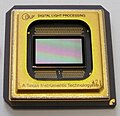
Micromirror array (DLP chip) from Texas Instruments in a housing
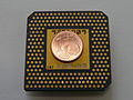
Rear of the housing with connection contacts


Digital Light Processing ( DLP , English ) is one of the US company Texas Instruments developed (TI) and as a mark registered projection technology , with the generated images are by a digital image is modulated onto a light beam. The light beam isbroken downinto pixels by a rectangular arrangement of movable micromirrorsand then reflected pixel by pixel either into the projection path or out of the projection path.

The heart of this technology, the component that contains the rectangular arrangement (matrix) of mirrors and their control technology, is referred to as DMD - Digital Micromirror Device (in German: " Digital Micromirror Unit").
In contrast to other methods in which a real image or a real object is imaged directly optically , here - similar to laser projection - the image is optically only generated within the projection path . Therefore, strictly speaking, it is not a projection as it is defined in physical optics .
DLP is used, for example, for video projectors and rear projection screens in the home theater and presentation area; and under the name "DLP-Cinema" in the digital cinema sector. DLP is also used in the industrial sector for additive manufacturing .
The technology has been licensed to various manufacturers.
Digital micromirror device

A central component of DLP projectors is a microsystem called a Digital Micromirror Device (DMD) . This is a spatial light modulator , (SLM, surface light modulator ). This consists of micromirror actuators arranged in the form of a matrix , i.e. tiltable reflective surfaces with an edge length of around 16 µm. The movement is caused by the force of electrostatic fields. Each micromirror can be individually adjusted in its angle and usually has two stable end states, between which it can switch up to 5000 times within a second. The number of mirrors corresponds to the resolution of the projected image, whereby a mirror can represent one or more pixels. DMD chips with resolutions of up to 4096 × 2160 pixels ( 4K ) have been available since 2010 .
Since the introduction of DMD technology, an important aspect of the further development of the technology has been, in addition to an increase in resolution, an improvement in contrast. To this end, two improvements in particular were developed by around 2002, which are referred to as “ small rotated via ” (SRV) and “ small mirror gap ” (SMG). The via is the tubular structure that connects the mirrors to the substructure. Here, a reduction in the size of this hollow component has led to fewer reflections / scattered light and thus to a 50 percent improvement in the contrast. The light falling between the mirrors and reflected by the substructure could be reduced by reducing the distance between the mirrors using SMG (30% increase in contrast), which at the same time improved the filling ratio. Finally, a new, inorganic coating of the metallic substructure called "Dark Metall 3" was introduced. Another change to improve the contrast was the increase in the tilt angle of the mirrors from 10 ° to 12 °.
These improvements were apparently integrated into the "Darkchip 2" introduced in 2004. The subsequent "Darkchip 3" introduced in 2005 continued the above measures. According to Texas Instruments, the “Darkchip 4” presented at the end of 2007 brought a further increase in contrast of 30% through advances in lithography and other process changes. In 2011, the majority of models with the Darkchip 2 or the Darkchip 3 are on the market; the Darkchip 4 was less popular.
In autumn 2015, Texas Instruments presented a new DMD with a resolution of 4 million pixels and a diagonal of 0.7 inches for low-cost 4K projectors. The chip is moved back and forth between two positions by a mechanism in order to be able to display the 8 million pixels present in 4K in two offset partial images.
Factors that determine the contrast of a particular projector include the actual DMD and the like. a. also the iris used, the light generating and bundling part, the light trap (absorber) for the deflected light as well as the compensation and low reflection of glass and other surfaces in the lens.
Image generation

Different brightness levels of the individual pixels are generated via a binary pulse-width-modulated control of the mirrors. To display 32 (= 2 5 ) brightness levels, for example , 5 states are required. These differ in how long the DMD is switched on (see also binary code and dual system ). In the first state ( bit 0) the mirror is on or off for the shortest possible time (1 or 0). With the next state (bit 1) the time doubles and so on. The total time for one cycle is a total of 496 µs with 5 bits. The principle is illustrated in the adjacent drawing. In practice, a slightly modified control is used for a better visual representation. All bits except for bits 0 and 1 are divided into individual sections that are distributed over the entire cycle (so-called bit division). This corresponds roughly to the pulse density modulation .
Color representation
Since the DMD chips reflect the white light from the projection lamp, additional steps are required to produce a color image. There are two ways of doing this: one-chip and three-chip technology.
One-chip technology


In a projector using one-chip technology (also called monochip technology), a color wheel is switched in the light path in front of the DMD chip, on which the color filters of the primary colors (usually red, green and blue, but sometimes others) rotate. In order to achieve better brightness values in white, a white sector can also be added to the color wheel. Depending on the position of the color filter, the electronics change the partial image that is reflected by the DMD. Due to the speed of rotation of the color wheel and the sluggishness of the human eye , the partial images are added to form a colored image impression. Since the recognition frequency differs from person to person, there were reports of a so-called rainbow effect , especially with the first models ( x1 ) , which occurred when the viewer perceived the individual colors. Therefore, in a first step, the number of revolutions of the wheel was doubled ( x2 ) and in newer models the color segments were increased from 4 (RGB and white) to 7 (2 × RGB and 1 × white) ( x4 ).
A dark green sector seems to be able to counteract color noise in dark image areas.
In order to increase the gamut and the image brightness (up to 50% luminance gain), Texas Instruments has been offering a technology marketed under the name "BrilliantColor" since 2005, in which the coordination between the mirror circuits of the DMD and the color wheel allows more options . Originally, color wheels were provided with three equally sized color segments in red, green and blue. However, this restriction meant that particularly strong tones in the colors in between, e.g. B. yellow, could not be displayed correctly. In addition, filtering those parts of the lamp's light spectrum that are not red, green or blue resulted in a loss of brightness. In contrast, BrilliantColor made it possible to use color wheels with more segments and in additional colors. In the original variant, these were, in addition to the above basic colors, cyan, magenta and yellow (see CMYK ). However, some manufacturers vary the colors and leave e.g. B. Magenta away in favor of a white sector. BrilliantColor enables a flexible selection of color segments, e.g. B. also RGBRGB. Even when using such color wheels, an enlarged color space can still be displayed, as BrilliantColor allows the transition area between two color segments, in which two adjacent segments to “sweep” the DMD at the same time, to be used for color mixing. Originally an expensive technology, Texas Instruments incorporated the BrilliantColor control into cheaper chipsets from 2007, so that the technology is now widely used.
A fundamental problem with display devices (not only projectors, but also televisions) with an extended color space such as BrilliantColor is, however, that the video material is recorded on Blu-ray discs with the significantly narrower color space BT.709. Therefore, BrilliantColor projectors that are supposed to play Blu-ray films do not initially benefit from the extended color space. In order to use the extended color space, the projector manufacturers use algorithms that map the colors of the BT.709 to a larger color space. This usually leads to stronger colors, especially with the secondary colors cyan, yellow and magenta, but carries the risk of an unnatural color representation ("wild gamut"), which can also deviate from the intentions of the director of a film (the one when converting Film on Blu-ray had to make compromises in terms of color representation). In the digital cinema , the films are therefore encoded with a considerably wider color space ( DCI / P3 ) defined by the Digital Cinema Initiative .
Another technique for expanding the color space and contrast is the dynamic control of the projection lamp. This control takes place per color wheel segment and thus allows the brightness of each of the colors used in the color wheel to be individually adjusted up and down, in addition to the brightness determined by the mirror oscillations. The technology is marketed by Osram under the name "UniShape" and by Philips as "VIDI".
With individual projectors, the end user can exchange the color wheel for one with a different color assignment, which allows more flexible use.
Three-chip technology
In a projector with three-chip technology, the light after the lamp is broken down into the three basic colors red, green and blue with dichroic mirrors and distributed individually to three DMD chips. The respective partial reflection of the individual DMDs is added back to the complete color image in a so-called dichroic prism , which contains two crossed dichroic mirrors. The rainbow effect cannot occur with these models. Due to the significantly higher price compared to single-chip models, these devices are mainly used in film studios, cinemas and other color-critical applications due to their high color fidelity. The disadvantage, however, is that the image is only composed of three individual colors. When it comes to color wheels, each manufacturer can decide for themselves which segments should be given which color. This means that offset colors can also be projected. At the beginning of 2012 a three-chip projector for cinemas was demonstrated for the first time, in which the lighting is carried out not by lamps but by three lasers. This approach can produce a brighter image. Improvements in sharpness (probably due to the elimination of oblique rays), contrast (elimination of scattered light) and color range (purer primary colors in lasers) are stated as further advantages. A market launch could take place by 2015, whereby the costs for cinema operators are currently still too high and regulatory problems and problems with "speckles" in the picture have to be solved.
Pros and cons / artifacts
Thanks to the more direct light path compared to LCD technology and the lack of polarization of the light, higher output light outputs are achieved than with an LCD projector. If you compare the image of a DLP projector with that of an LCD projector, you will notice the softer rasterization of the image, which has a positive effect on the impression. Thanks to the large angle of inclination of the micromirrors, high contrast values are achieved. In addition, the DLP technology switches in the microsecond range so that trailing effects are avoided. This is particularly noticeable in stereo 3D mode, in which, thanks to the rapid switching, no “ghost images” (cross-talk between the left and right 3D image) are generated.
In dark image areas, DLP projectors can show a noise that “looks like a fine swarm of flies” and that is caused by the different timing of the individual mirrors.
Older single-DMD chip projectors show a rainbow effect at high-contrast transitions (mostly black and white) , especially when the images change quickly or the eyes quickly roam over the image. The basic colors of the color wheel become visible on the contours of the object, which can be very disturbing for many viewers. You can see this effect even more clearly if you stretch your hand into the beam path, spread your fingers and move them back and forth.
Manufacturers try to reduce this effect by using color wheels with more than three segments or with a higher speed. Devices that use three sets of different colored LEDs instead of a color wheel should no longer show a rainbow effect due to the higher switching speed possible with LEDs. A test in 2011, however, showed rainbow effects that were still "clearly noticeable" on a number of LED DLP projectors.
In the case of 3D projectors (which project the images for the left and right eye alternately one behind the other), the ability to switch between images more quickly is an advantage compared to LCD and LCoS projectors, as this allows crosstalk between the images (with one eye at least seeing part of the image intended for the other eye) can be avoided. However, crosstalk can still occur due to the shutter glasses used .
lifespan
In contrast to LCD technology , DLP projectors are less or not at all affected by fading and burning in colors. The color wheel, which rotates constantly during projection, has a service life of approx. 20,000 hours - not because the colors are fading, but because of the motors, whose service life is limited by the bearings. In contrast, the LCD panels or the polarization filters of LCD projectors are faded after 4,000 to 6,000 hours and are no longer suitable for use. Because a lower light intensity is required, the light sources of the DLP projectors also have a service life of up to 6,000 hours, after which they must be replaced. Depending on the projector manufacturer, an accumulation of "dead pixels" can be seen after a few thousand operating hours.
See also
- LCoS : reflective liquid crystal chip
- Grating Light Valve : Image generation by diffraction on a chip
Web links
- Texas Instruments website about DLP technology (German)
- Introduction to DMD technology from Texas Instruments (English; PDF; 616 kB)
- Cinefreaks - DLP in the cinema
Individual evidence
- ↑ Andreas Gebhardt: Generative manufacturing processes. Munich 2013, ISBN 978-3-446-43651-0 , pp. 115, 135.
- ↑ Plano Cinema Firm To Open Theater With Digital Projection, Self-Serve Snacks. (No longer available online.) Texas Business on October 25, 2010, archived from the original on January 26, 2012 ; accessed on October 24, 2011 . Info: The archive link was inserted automatically and has not yet been checked. Please check the original and archive link according to the instructions and then remove this notice.
- ↑ [1] ( Page no longer available , search in web archives ) Info: The link was automatically marked as defective. Please check the link according to the instructions and then remove this notice.
- ↑ [2]
- ↑ CES 2004 report, p. 38 ( PDF ( Memento of the original from March 1, 2013 in the Internet Archive ) Info: The archive link has been inserted automatically and has not yet been checked. Please check the original and archive link according to the instructions and then remove this note. )
- ↑ [3] ( page no longer available , search in web archives ) Info: The link was automatically marked as defective. Please check the link according to the instructions and then remove this notice.
- ↑ [4]
- ↑ Archive link ( Memento of the original from November 17, 2015 in the Internet Archive ) Info: The archive link was inserted automatically and has not yet been checked. Please check the original and archive link according to the instructions and then remove this notice.
- ↑ [5]
- ↑ [6]
- ↑ [7]
- ↑ [8]
- ↑ [9]
- ↑ PDF at www.spectracal.com
- ↑ [10] ( page no longer available , search in web archives ) Info: The link was automatically marked as defective. Please check the link according to the instructions and then remove this notice.
- ↑ PDF at www.lighting.philips.com ( Memento of the original dated February 6, 2011 in the Internet Archive ) Info: The archive link was inserted automatically and has not yet been checked. Please check the original and archive link according to the instructions and then remove this notice.
- ↑ [11] ( Page no longer available , search in web archives ) Info: The link was automatically marked as defective. Please check the link according to the instructions and then remove this notice. E-Vision WXGA 600
- ↑ [12]
- ↑ Archive link ( Memento of the original dated February 8, 2012 in the Internet Archive ) Info: The archive link was inserted automatically and has not yet been checked. Please check the original and archive link according to the instructions and then remove this notice.
- ↑ [13]
- ↑ [14]
- ↑ c't magazine for computer technology, 24/2011, p. 98; ISSN 0724-8679
- ↑ [15] ( Page no longer available , search in web archives ) Info: The link was automatically marked as defective. Please check the link according to the instructions and then remove this notice.
- ^ The affordable solution for the DLP TV white dot problem - DLP Lamp Guide - LCD and DLP Repair Tips - Fix Your DLP - FixYourDLP.com . In: DLP Lamp Guide - LCD and DLP Repair Tips - Fix Your DLP - FixYourDLP.com . June 1, 2012 ( fixyourdlp.com [accessed November 12, 2017]).