
Drainage (technical systems)

With drainage , and drainage , more Germanized drainage , referred to measures using technical systems and these systems itself, the water logging on buildings and counteract on agricultural land. For this purpose, the water is recorded and drained off in a targeted manner. This waterlogging can have different causes:
- high water table ,
- Extraneous water inflow,
- Backwater ,
- Adhesive water .
In the case of agricultural use, changes in the type of use come into consideration as further causes, such as the extensification of areas, which leads to less plant growth and thus less evaporation of the plants, or the transition to irrigation, which can require the discharge of excess water.
Pipe drainage is the most common technical system . In special cases, drilled wells or seepage are used, for example. B. in the absence of free drainage. The special requirement for special structures to create both support systems and drainage systems can advantageously be solved by a drainage wall.
Drainage for structural purposes

Basics
The drainage on structures can be considered as a protective system if seepage and stratum water are to be kept away from the bed ( foundation ) and the walls in contact with the ground. If the groundwater level is consistently higher than the bottom, the structure must be watertight, e.g. B. by a black or white tub .
The selection and dimensioning of technical drainage systems requires knowledge and consideration of various influences:
- Water balance with knowledge of the soil water content in the drainage area as well as the inflow and outflow of water in the area to be protected,
- Location of the water table
- Soil parameters, especially the saturated and partially saturated hydraulic conductivity , given as flow length per unit of time , usually in m / s,
- Drainage geometry with the extent and height of the surfaces; Possibilities for the spatial arrangement of the drainage systems (drainage geometry) and the discharge of the accumulating water (depth of the pipes)
An exact computational determination requires the solution of differential equations , for which mostly computer programs are used. In addition, usage formulas are used, such as B. Hooghoud's formula .
The disciplines of hydrogeology and soil science deal with framework conditions that can limit the effectiveness of drainage systems in the long term. The function of drainage can be impaired by the redistribution of fine soil particles in the soil by water ( suffosion ) . Non- cohesive soils from a certain degree of non-uniformity and especially those with a grading curve with failure granulation are affected . The relocation can lead to a reduction in the permeability of the soil structure ( colmation ) and drainage measures. Suffosion is counteracted with soil filters , observing the filter rules, and with geotextiles .
Regulations and construction work
The requirements for drainage systems for buildings are compiled in DIN 4095. Regardless of this, the building waterproofing must be ensured, the technical solutions and requirements of which are specified in DIN 18195 .
Functional drainage on structures is achieved by surrounding the parts of the structure in contact with the ground with a water-permeable layer (usually gravel, drainage mats, drainage filter socks or other artificial drainage elements ) from which the drainage pipes drain the water. The drainage layer is protected against the subsoil by a layer of fleece against silting up with fine material. More stringent requirements are placed on drainage pipes for buildings and structures than on drainage pipes in agriculture. According to DIN 4095, they should withstand a slight overpressure of 0.2 m water column, which is why stiffer pipes in the form of rods (instead of rolls) are required, e.g. B. Plastic pipes made of PVC (polyvinyl chloride) hard according to DIN 1187 Form A or DIN 4262-1.
The introduction of drainage water into the mixed sewer system is not permitted due to the increased hydraulic load on the sewage treatment plants. Discharge into the rainwater sewer system is subject to approval. Details are regulated in the municipal drainage statutes.
Special drainage systems for structural purposes
Drainage post

The drainage pile combines the properties of piles and wells . In this way, one component enables the load to be introduced into the subsoil while simultaneously managing the groundwater by pumping out or discharging it.
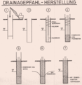
Manufacture of the drainage pile

Filter pipe and reinforcement

finished drainage post


To produce a drainage pile - as in the case of a bored pile - a cased hole is first sunk and the soil inside is excavated. Then the filter pipe (e.g. slot bridge pipe) is installed together with the pile reinforcement. In the lower area of the drainage pile, drainage concrete is poured as single-grain concrete with a diameter of 4–8 mm. Above that, the rest of the pile is concreted with a conventional concrete . The piping is pulled up in sections and removed. After hardening, the drainage pile can take on its function both for load transfer and for water regulation.
Drainage wall
Similar to a drainage pile, the principle can also be applied to a diaphragm wall , which thus becomes a drainage wall . This enables a type of construction that is very space-saving by connecting the support and drainage functions and can be advantageous in confined spaces.

Two-sided drainage wall
Drainage wall on one side

View of excavation with drainage wall


Drainage anchor
In the case of natural slopes, the slope water that occurs can become problematic if a cut is to be made in the slope or a construction pit is to be made on the slope , since the slope water flowing in creates a water pressure that can lead to water leakage.
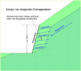
Section of construction pit with drainage anchors

Detail of head formation drainage anchor

Detail picture of filter mortar


Drainage anchors with a filling of drainage mortar offer a solution for this by collecting and draining slope water deep in front of the cut. This also reduces the pore water pressure and stabilizes the slope. During the execution, it is essential that the drainage anchors are drilled into the subsoil with an incline so that the water to be drained can also flow away through the drainage mortar without pressure.

Drainage anchors of this type are installed in slopes up to a depth of 14 m in excavation pits on slopes, in slope constructions and behind retaining walls and are advantageously used in a wide variety of soil types - from debris to fine-grained layers to fissured rock. The above example shows a construction pit protection in the high mountains with a height of approx. 20 m and a construction pit length of approx. 120 m. The slope water could be collected and discharged up to 10 m behind the construction pit with the built-in drainage anchors.
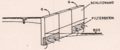
Drainage of tunnels

1 outer tunnel shell, 2 seal, 3 inner tunnel shell, 4 annular gap, 5 filter zone, 6 drainage collecting line, 9 tunnel water collecting line, 8 overall drainage line
Tunnels often also cut through water-bearing layers, so that the reliable reduction in water pressure and the drainage of the water that occurs is important for operational safety. Usually, water that accumulates in the annular gap between the inner and outer shell of a tunnel is drained to the lateral base points and flows there via a filter layer into a drainage line. A problem that frequently occurs with this type of drainage of tunnel structures is sintering, with deposits impairing water permeability. This limitation has various causes and can be reduced by selecting more suitable geotextiles as filters in the annular gap, by using gravel with a reduced addition of cement (less than 200 kg / m³) for the filter layer and by using drainage pipes with larger inlet openings.
Drainage on river dikes
Drainage can be used as a safety measure on existing river dikes in order to counteract the increasing number of dike breaches that occurred in the recent past after extreme flood runoff ( Oderhochwasser 1997 , Elbehochwasser 2002 , Elbehochwasser 2006 ). Many river dikes in Germany have a long history. They usually have embankments that are too steep and no zoning in the seal, support and drainage bodies, so that the improvement of these dikes will be necessary in the future . Floods can cause three different types of dike breaches: by overflowing, by seeping through or by undercurrent.
Leakage can be reduced by draining the dike flanks on the land side. Depending on the permeability and pre-moisture of the dike body, prolonged damming - intensified by irregularities such as loosening areas or animal structures - leads to moisture penetration, which lowers the grain-to-grain tension and endangers the stability of the landside embankment through flow forces.
Landfill drainage
In the case of waste landfills, drainage is an important part of the drainage system, with which the resulting seepage water is drained from the landfill body as quickly as possible and fed to wastewater treatment. This is to prevent overflow in the landfill body and to protect the base seal. This drainage system consists of the surface drainage, the drainage pipes and possibly inspection shafts and / or tunnels as well as storage basins located outside. Details are regulated in the Landfill Ordinance (DepV) , which replaced the previously applicable TA Abfall and TA Siedlungsabfall in 2009 . A gravel layer of at least 30 cm thick made of round grain of grain group 16/32 has been specified as surface drainage. According to TA waste, the calcium carbonate content should not be more than 20% by weight in order to prevent sintering. The drainage lines should therefore have sufficient resistance, stability and deformability (to adapt to subsidence). The lines should be controllable and flushable: a minimum diameter of DN 250 and lines made of PE-HD ( high-strength polyethylene ) are provided.
In the long-term operation of drainage systems in landfills, incrustations can occur due to the precipitation of poorly soluble compounds that narrow the pipe cross-section. The causes lie in chemical-physical processes that are triggered by a change in the pH value , the partial pressure of the carbon dioxide or the access of oxygen , and in the microbiological degradation processes of the methane-forming and sulfate-reducing bacteria , which create an alkaline environment in their immediate environment and thus a precipitate of various types Evoke salts.
This operational problem can be prevented by appropriate construction of the drainage systems such as the lowest possible calcium carbonate content in the surface drainage as well as well controllable and flushable pipes.
Gas drainage, with which the resulting landfill gas is discharged, is a special form of drainage from landfill sites. To this end, combined systems have been installed in municipal waste landfills, with which leachate and landfill gas are collected and discharged. With the end of the dumping of untreated waste, such landfills have no longer been permitted in Germany since 2005. Since then, they have been locked and enclosed with external sealing systems. This also includes a gas drainage system that lies under the waterproofing membrane and retains rainwater. The requirements are regulated in the Landfill Ordinance of 2009 .
Drainage of sports surfaces
Extensive drainage is often used on lawns and play areas in sports facilities. The goals are similar to those for agricultural use: after rainfall, rapid use should be possible and the drainage of excess water should be ensured when irrigation is usually required. Examples: Allianz Arena Munich and Rheinstadion Düsseldorf .
Drainage for agricultural purposes
aims


Drainage systems are used in agriculture to increase yield by draining excess soil water. There can be various reasons for this:
- Increase in productivity by facilitating management (access),
- as a prerequisite for further improvement measures (soil amelioration by deep plowing depth or loosening),
- Change of use, especially when converting grassland to arable land,
- Prevention or reduction of salinity (especially with irrigation)
activities
Drainage measures in the agricultural sector are differentiated according to the purpose and arrangement of the systems:
- systematic drainage (arrangement of several parallel drainage pipes),
- Demand drainage (drainage of sinks, source outlets and the like),
- Catching drainage (recording of laterally flowing groundwater and / or laterally flowing water close to the surface).
In the agricultural use of drainage, pipe drainage is mostly used; only in special cases, such as the lack of natural drainage, are drilled wells and drainage pumps used .
Advantages of a functioning drainage system
- If the soil is soaked, this damages the soil structure and soil life. With drainage, you can reach even and fertile soils, which are the basis for safe, high yields.
- Waterlogged soils can often not be driven on or only inadequately and with a delay. A drained, dry field can be processed at the optimal processing date. This lowers the cost of job completion and the cost of crop protection.
- Nutrient leaching is increased in too wet soils. A drained field can save fertilizer costs.
- With drained and evenly rooted soils, the farmer achieves uniform crops, which facilitate inventory management and deliver a homogeneous harvest.
- Drained soils can absorb more rainwater and reduce soil loss through erosion.
Pipe drainage
During drainage, the water is collected in perforated pipes (technically "suction devices") and fed to larger pipes (collectors). In both sections, the inflow of water takes place under hydraulic pressure, so the term teat is slightly misleading. The collectors flow into trenches and streams (technically receiving waters ). Non-return valves are usually used at the outflows of collectors, on the one hand to hold back water and on the other hand to hold back animals (hence also called frog valves ). Nowadays, plastic pipes are commonly used as pipe systems that are corrugated on the outside (higher load-bearing capacity with improved flexibility at the same time) and smooth on the inside (improved water drainage, reduced deposits). The water enters the pipes through narrow slots as inlet openings, which are located in the wave troughs of the outer ribs for protection and have a width between 0.6 and 1 mm and a length of 0.6 to 2 mm. These pipes are available with diameters between 50 and 400 mm and are supplied in rolls of up to 300 m in length. The pipes can be surrounded with filter material (drainage filter hose) in order to reduce the silting up of fine material ( especially clay and silt components ), to reduce the entry resistance at the openings and to protect the pipes from mechanical pressure.

Laying of drainage pipes

Laying drainage on a grassland area
Drainage pipes "on demand"

Drainage pipe - close-up

Drainage pipe with filter coating

Laying machine in use


Rating

In the technical design of drainage systems, the spatial conditions with the extent and height of the areas are taken into account as drainage geometry. The properties of the soil are recorded using the water conductivity of the soil layers, subdivided into saturated and partially saturated hydraulic conductivity (parameter of flow length per unit of time, mostly m / s). In addition, there is the depth of the pipes and the groundwater level. The exact computational determination is connected with the solution of differential equations , which is correspondingly complex. For the dimensioning of drainage systems, in addition to the use of computer programs, the use of usage formulas is common, such as the calculation approach by Hooghoud, in which the aforementioned decisive influencing variables lead to a dimensioned water discharge that enables the pipe cross-section to be selected.
laying

The drainage pipes made of flexible plastic pipes ( geotextile filter sheathing made of coconut fibers until around the mid-1990s , then also with plastic fibers) have been laid for decades with special machines, which usually dig a narrow slot in the ground with a drainage plow and at the lowest point at 0.8 to 1 m lay the pipeline over an arched guide. Trenchers are used less frequently, digging a narrow trench with a circumferential chain and milling system into which the pipe is laid. In the case of large differences in height, it may be necessary, especially for drain collectors, to lay them at a greater depth, which requires dredging work.
Melioration by mole plow

With this drainage a narrow ploughshare is pulled through the ground, at the lower end of which there is a pressing head, which leaves a tubular cavity in the ground. This method is figuratively referred to as mole drainage and can be used in cohesive, sufficiently plastic soils. The depth of these tubes is about 60 cm, their distance about 2 m.
history
Drainage from agricultural areas is known from ancient times. In excavations, the traditional stone drainage has been proven. From 1650 onwards, drainage systems with wooden and stone pipes are used in England. Shortly afterwards, this technology was also used in Germany. More extensive drainage measures under the concept of amelioration were started in Germany in the 19th century. These activities were comprehensively analyzed and described for areas in the Prussian provinces of Westphalia and Brandenburg between 1830 and 1880 as part of a dissertation. The starting point was structural reforms, in which the previously only extensively used and usable commons were opened up for private investments, among other things triggered by the price increases after the agricultural crisis of the 1820s. A three-phase process model has emerged for the implementation of this large-scale improvement, starting with the agricultural reforms, followed by an "incentive system" with associations, agricultural schools, model farms and bonuses. In the third phase, large state-planned and controlled land improvements could be implemented with more extensive financial resources and new legal bases.
The implementation of the measures could be traced in detail on the basis of the documents, including the ecological effects with a radical change in regional hydrology through irrigation and drainage measures as well as the disappearance of formerly extensively used landscapes, such as moor and heather areas. Drainage is a major intervention in the ecosystem , as the drainage of the groundwater level is lowered more or less over a large area and the vegetation changes. So z. B. Wet meadows and salt areas, which harbor rare species and have a high biodiversity, are destroyed by drainage.
Around 1840 the first clay pipes were developed and laid by hand. These clay pipes were further developed until the 1960s and have also been laid by machine since the 1940s.
In the 1960s, the use of plastic pipes began, primarily of inexpensive PVC pipes, which initially had longitudinal slots sawn in, then were made with wavy walls and punched openings.
The construction of drainage systems in the agricultural sector has declined significantly in Germany since the 1980s, but is still very important in those countries that increase their agricultural productivity, especially when using irrigation systems or for converting agricultural land. Surveys at the end of the 1990s assume that around eleven percent of the agricultural area in Germany is equipped with drainage systems. In Austria the proportion is around seven percent and in Switzerland around eight percent.
See also
literature
Historical
- J. Kopecký: Soil investigation for the purpose of drainage works. Prague 1901.
- F. Merl: New theory of soil drainage. Ansbach 1890.
- L. Vincent, O. Vincent, G. Abel: The drainage, its theory and practice. 6., completely new. Edition. Leipzig 1882.
- L. Vincent: Irrigation and drainage of fields and meadows. 3. Edition. Berlin 1890.
Current
- Rudolf Eggelsmann: Drainage instructions for agriculture, civil engineering and landscaping. 2nd Edition. Paul Parey Verlag, Hamburg / Berlin 1981, ISBN 3-490-15216-6 .
- John Richard Landon (Ed.): Booker tropical soil manual: a handbook for soil survey and agricultural land evaluation in the tropics and subtropics. Routledge, 2014, ISBN 978-0-582-00557-0 .
- Kurt Lecher, Hans-Peter Lühr, Ulrich Zanke: Pocket book of water management. 8th edition. Parey Buchverlag, Berlin 2001, ISBN 3-8263-8493-8 .
- Lambert Smedema among others: Modern Land Drainage - Planning, Design and Management of Agricultural Drainage Systems. 2nd edition. Balkema, Leiden / NL 2004, ISBN 90-5809-554-1 .
- Udo Quentin, Johannes G. Schwerdtle: Drainage in agriculture. 1st edition. DLG Verlag, Frankfurt am Main 2013, ISBN 978-3-7690-2029-8 .
Web links
Individual evidence
- ↑ a b c d Kurt Lecher, Hans-Peter Lühr, Ulrich Zanke: Pocket book of water management. 8th edition. Parey Buchverlag Berlin 2001, ISBN 3-8263-8493-8 .
- ↑ Bernhard Wietek : Dränageverbau. In: Civil engineering-civil engineering-road construction. 05/83, 1983, pp. 322-327.
- ↑ K. Simmer: Foundation. Part 2: Construction pits and foundations. 18th edition. BG Teubner, 1999.
- ^ Bernhard Wietek: Drainage Walling as Excavation Support. 2nd Int, Conf. On Case Histories in Geotech. Engineering, June 1988, St. Louis, USA, Paper 5.03.
- ↑ Bernhard Wietek: Unique drainage anchor application. In: Österr. Construction newspaper. 9/2008, pp. 33-35.
- ↑ Bernhard Maidl et al.: Experimental investigations to improve the drainage systems of traffic tunnels. (= Research Road Construction and Road Traffic Technology. Issue 858). Bonn 2002, ISBN 3-934458-87-4 .
- ↑ Institute for Soil Mechanics and Rock Mechanics, University of Karlsruhe: Stabilization of river dikes at risk of breaking with drainage elements for seepage water collection and reinforcement. Subproject 1: Geohydraulic studies of the mode of action of drainage elements. Karlsruhe 2009.
- ↑ Federal Ministry for the Environment, Nature Conservation and Nuclear Safety: Complete version of the second general administrative regulation for the Waste Act (TA Abfall) / Technical instructions for the storage, chemical / physical, biological treatment, incineration and deposit of waste that requires special monitoring, Berlin 1991.
- ↑ Gerd Burkhard, Thomas Egloffstein (ed.): Landfill drainage systems - planning, construction, operation, damage and rehabilitation processes. Expert-Verlag, Renningen-Malmsheim 1995, ISBN 3-8169-1258-3 .
- ^ Meyer's Large Conversational Lexicon. Volume 5. Leipzig 1906, pp. 165-167.
- ↑ Jean Michel Joseph Leclerc: Handbook of Drainage or: Theoretical and practical instructions for draining moist soil. Emile Flatau, Brussels / Leipzig 1860. ( online in the Google book search)
- ↑ a b c Rita Gudermann: Morastwelt and Paradise. Economy and ecology in agriculture using the example of the melioration in Westphalia and Brandenburg (1830–1880). (= Research on regional history. Volume 35). Ferdinand Schöningh Verlag, Paderborn 2000, ISBN 3-506-79607-0 .
- ^ Federal Environment Agency (ed.): Salt habitats in Austria . (PDF; 3.8 MB) Vienna 2006, ISBN 3-85457-800-8 , p. 182.
- ↑ R. Bohn: The drainage pipe in its development and differences in shape and material. In: R. Eggelsmann: Drainage instructions for agriculture, civil engineering and landscaping. 2nd Edition. Paul Parey Verlag, Hamburg / Berlin, ISBN 3-490-15216-6 .
- ^ K. Bellin: Ten years of plastic drainage pipes. In: R. Eggelsmann: Drainage instructions for agriculture, civil engineering and landscaping. 2nd Edition. Paul Parey Verlag, Hamburg / Berlin 1972, ISBN 3-490-15216-6 .
- ↑ Lambert Smedema et al: Modern Land Drainage - Planning, Design and Management of Agricultural Drainage Systems. 2nd edition, Leiden / NL 2004.