Kappelmotor
The Kappel motor (PAD motor) is based on kinematics invented by Andreas Kappel in 1999, which efficiently converts linear movements into rotation. The patent for the "Kappelmotor" was taken over by Noliac A / S in 2010.
Working principle
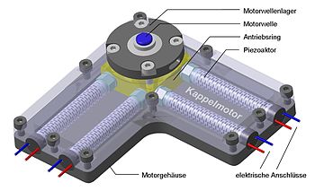
The kinematics consists of a drive ring which surrounds a rotatably mounted motor shaft, the drive ring having a slightly larger inside diameter than the outside diameter of the motor shaft. If the drive ring is displaced in a circle, the motor shaft rolls on the inner surface of the drive ring and is thereby set in rotation. Piezoceramic stacks can be used to generate the displacement movement . If a sinusoidal voltage is applied to one piezo actuator and a cosine voltage to the other piezo actuator , the 90 degrees phase-shifted sinusoidal mechanical deflections of the piezo actuators overlap to create the desired circular displacement movement of the drive ring . The direction of rotation is determined by the sign of the phase shift ± 90 °. The speed is determined by the frequency of the control signal.
Power transmission
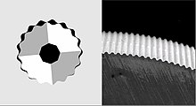
The contact surfaces of the shaft and the drive ring are provided with teeth for a form-fitting unwinding. As a result, the motor shaft can be positioned very precisely with high dynamics in every angular position even under high load torques. For this, backlash-free micro-toothing is used, which can be made of both metal and plastic. The reduction ratio results from the difference in the number of teeth of the drive ring and motor shaft to the total number of teeth on the motor shaft and can be from 1:10 to 1: several hundred. In order to guarantee constant meshing, the tooth height is smaller than the deflection of the piezo actuators. This results in tooth heights in the range of a few tens of micrometers in piezo stack actuators. Due to the cycloidal tooth shape, the steel micro-toothing is absolutely overload-proof and cannot be damaged by blockages. This also applies to plastic gears, which are reversibly elastically deformed in the event of an overload. The efficiency of the micro-toothed kinematics of the Kappel motor is approx. 95%.
Control
The simplest version of the Kappel motor consists of two piezo actuators attached at right angles to the drive ring . By using piezo stacks as actuators, the piezoelectric effect can be used to record load torques in real time, both with the engine running and with the engine stopped. Since the rotary position of the motor shaft is always synchronous with the absolute electrical phase , controlled open-loop operation is possible. This means that complex motion profiles, in which several individual drives are to work together in a coordinated manner, can be easily mastered. Electromotive servo systems require a large number of additional components such as gears , encoders , torque sensors or a motor brake as well as a closed control loop . These components can be omitted without replacement in the case of Kappel motors with corresponding control electronics.
Executions
Kappel motors can basically be implemented in planar and cylindrical designs. The torques range from a few millinewton meters to several tens of Nm.
Planar
Depending on the performance and housing requirements, the kinematics of the Kappel motor can be implemented in different material systems or combined with other actuators. An example of this is a pointer drive manufactured using plastic injection molding technology, in which the linear movements of two piezoelectric bending actuators are superimposed to form a circular displacement movement of the drive ring. The considerably larger working stroke of the piezoelectric bending actuators of a few ± 100 µm compared to stack actuators permits coarser tooth structures that can be produced by means of plastic injection molding .
Cylindrical
For cylindrical motor designs, the piezoelectric bending actuators are arranged along the motor shaft. To increase performance, two pairs of bending actuators are used that move the drive ring around the motor shaft. Alternatively, the drive shaft provided with a spur gear can also be displaced in a circle so that the spur gear rolls on the inner surface of the drive ring. For more powerful cylindrical Kappel motors, stack actuators are possible as actuators.
properties
Piezoelectrically driven Kappel motors have the following functional properties:
- High absolute positioning accuracy (arc seconds)
- Constant, speed-independent engine torque (several Nm)
- High dynamics (start / stop times less than 0.1 ms)
- Sensorless real-time recording of load moments
- Powerless position holding under load when switched on
- Large holding torque when switched off (i.e. without energy supply)
- Speed range from 0 to several hundred min -1
- Complete freedom from play and very high torsional rigidity (no gear required)
- Multiple Kappel motors can be easily synchronized
- Little wear due to rolling movement
- Scalability in terms of speed / torque characteristics (micro-toothing)
- Scalability in terms of material system (metal, plastic, composite materials)
- Function independent of magnetic field (e.g. in magnetic resonance tomographs)
- No generation of magnetic stray fields
application
Due to the possible open-loop operation, complex motion sequences, as they occur in robotics, can be easily mastered. Future areas of application are drive problems in which the focus is less on speed and more on torque , precision , simple control and dynamics , such as:
- Window regulators in motor vehicles
- robotics
- Pointer instruments
- Positioning tasks of all kinds
- Use in an environment exposed to radiation
See also
literature
- Kappel, B. Gottlieb, T. Schwebel, C. Wallenhauer: PAD - Piezoelectric Actuator Drive , Actuator 2006, 10th Int. Conf. on New Actuators, Bremen, Germany 2006, p. 457-460
- J. Rucha, H. Liess, J. Heinzl, A. Kappel, T. Schwebel, B. Gottlieb, C. Wallenhauer, T. Lüth: Applicability of a piezoelectric actuator drive as a sensorless high precision drive , Actuator 2006, 10th Int . Conf. on New Actuators, Bremen, Germany 2006, p. 636-639
- A. Kappel, B. Gottlieb, T. Schwebel, C. Wallenhauer, M. Vogl, J. Rucha, T. Lüth: PAD - A micromechatronic drive system with unusual properties , VDE Verlag, GMM, Fachbericht 54, 2007, p. 147-152
- C. Wallenhauer, B. Gottlieb, A. Kappel, T. Schwebel, J. Rucha, T. Lüth: Accurate Load Detection Based on a New Piezoelectric Drive Principle Employing Phase-Shift Measurement , IEEE Journal of Micromechanical Systems, Vol. 16, No. 2, April 2007, doi : 10.1109 / JWEMS.2006.889536 , p. 344-350
- R. Keller, A. Kappel, B. Gottlieb, T. Schwebel, C. Wallenhauer: PAD-Piezoelectric Actuator Drive, new high precision and sensitive actuator system , PCIM Europe 2007, Nuremberg, May 22. - 24., Germany
- A. Kappel, B. Gottlieb, C. Wallenhauer: Piezoelectric actuator (PAD) , at - Automatisierungstechnik 56 (2008) 3, doi : 10.1524 / auto.2008.0693 , Oldenbourg Wissenschaftsverlag, p. 128-135
- R. Drawfussl, B. Gottlieb, C. Wallenhauer, A. Kappel, M. Vogl, T. Kraus, T. Lüth: Synchronously Controlled Piezoelectric Actuator Drives (PAD) as Motors of a Delta-3 Robot , Actuator 2008, 11th Int . Conf. on New Actuators, Bremen, Germany 2008, June 9. - 11., p. 125 - 128
- A. Kappel, B. Gottlieb, C. Wallenhauer, R. Zeichenfüßl, M. Vogl, T. Kraus, T. Lüth: PAD - A Scalable Drive Technology , Actuator 2008, 11th Int. Conf. on New Actuators, Bremen, Germany 2008, June 9. - 11., p. 558-561
- M. Vogl, T. Kraus, R. Maßfüßl, C. Wallenhauer, B. Gottlieb, A. Kappel, T. Lüth: Development of a MRI-safe Piezo Actuator Drive (PAD) , Actuator 2008, 11th Int. Conf. on New Actuators, Bremen, Germany 2008, June 9. - 11., p. 576-579
- M. Vogl, T. Kraus, R. Maßfüßl, C. Wallenhauer, B. Gottlieb, A. Kappel, T. Lüth: Construction and measurement of the rigidity of the high-precision PAD-Delta3 robot with piezo rotary drives , Robotik 2008 Congress, Munich, June 11 . - 12., p. 63-66
- T. Kraus, M. Vogl, R. Drawfussl, C. Wallenhauer, B. Gottlieb, A. Kappel, T. Lüth: Control for the PAD-Delta3 robot based on a digital signal processor , Robotik 2008 Congress, Munich, June 11. - 12., p. 269-271
- C. Wallenhauer, A. Kappel, B. Gottlieb, R. Drawfussl: PAD - New drive technology with high functional density for robotics , IFM International Mechatronics Forum 2008, September 22nd - 23rd, Stuttgart
- A. Kappel, B. Gottlieb, C. Wallenhauer, R. Drawfussl: New micromechatronic PAD precision actuators - more than an alternative to electric motors? , VDE Congress 2008, Munich, November 3rd - 5th
- M. Vogl, T. Kraus, R. Maßfüßl, C. Wallenhauer, B. Gottlieb, A. Kappel, T. Lüth: Broaching of Microteeth for a PAD - Piezo Actuator Drive , 9th International Conference of the euspen, San Sebastian, Spain 2009, June 02.-05., P. 503-506
- M. Vogl, T. Kraus, M. Peller, R. Maßfüßl, C. Wallenhauer, B. Gottlieb, A. Kappel, T. Lüth: PAD - Piezo Actuator Drive for Employment in a Magnet Resonance Imaging Device , Worldcongress 2009, Munich , Germany 2009, Sept. 07.-12., P. 271-273
- R. Drawfussl, T. Glaßner, A. Kappel, T. Lüth, M. Vogl, C. Wallenhauer: Testing the service life of a novel piezoelectric actuator (PAD) , SPS / IPC / DRIVES, Nürnberg, Germany 2009, 24.-27 . Nov., p. 239-247


