
Radio data system
The R adio D ata S ystem ( RDS ; English , literally translated: radio data system ) enables the transmission of additional digital information for analogue VHF radio .
history
The Institute for Broadcasting Technology (IRT ) played a key role in the development of the Radio Data System (RDS) as part of the work of the European Broadcasting Union (EBU). The first attempts at broadcasting took place in 1983 via VHF transmitters of Bavarian Radio. Its technical director, Frank Müller-Römer , provided significant support for the system development and the broadcast attempts. The RDS test operation began in 1984, the official introduction was April 1, 1988.
The radio data system is standardized in DIN EN 62106. The currently valid version is EN 62106: 2010-07 (German version), which replaces the 2002 version. The RDS Forum (Geneva) has maintained the RDS standards since 1993, independently of the EBU.
The first car radio with RDS was the Volvo SR-701 radio, available for an extra charge in the Volvo 760 . In the beginning, RDS detection was mainly used in car radios , since the transmission of alternative frequencies makes it possible to automatically change the frequency without user intervention and thus to follow a program that has been set once. This saves the manual search for the new frequency if the vehicle leaves the transmission range of a transmitter while driving . The RDS signal is usually generated specifically for each transmitter location, mostly directly at the transmitter.
At its annual meeting in Glion on June 9, 2015, the RDS Forum decided to bring the new RDS2 standard on its way. The standard is being drawn up in close cooperation with our US colleagues from the NRSC RBDS Subcommittee and is intended to provide a uniform platform for FM broadcasting and worldwide data services. RDS2 was submitted as IEC 62106 Edition 4 as the new standard in 2017.
Under RDS protocol is now understood 1984-2016. RDS and RDS2 are called the new versions, whereby RDS is the backward compatible part with the usual 1187.5 bits per second and works with conventional receivers. RDS2 requires new chips or chipsets and has a data rate of up to 4750 bits per second.
New structure of IEC 62106 Edition 4 2017
RADIO DATA SYSTEM (RDS) - VHF / FM SOUND BROADCASTING IN THE FREQUENCY RANGE FROM 64.0 MHz TO 108.0 MHz
- Part 1: RDS system: Modulation characteristics and baseband coding
- Part 2: RDS message format, coding and definition of RDS features
- Part 3: Coding and registration of Open Data Applications ODAs
- Part 4: Registered code tables
- Part 5: Marking of RDS and RDS2 devices
- Part 6: Compilation of technical specifications for Open Data Applications in the public domain
- Part 7: RBDS
- Part 8: Universal Encoder Communication Protocol UECP
Note to
- P7: RBDS will only describe the differences between RDS and RBDS. It is primarily about generating the PI code.
- P8: UECP used to be its own standard, now it is included in IEC 62106. RDS2 starts with version 8.0
Versions up to 7.x remain valid for the old or 1 carrier RDS. (57kHz - Stream 0))
Services of the RDS
The services of the RDS are certain types of data that are sent and evaluated by the radio receivers according to the type of data. When the data is sent in send blocks (see below for the format), the service is partially defined by the group type (GT). 16 group types are available in two versions, A and B, for a total of 32.
In addition to the widely used functions for program identification, traffic information and alternative frequencies, RDS offers other options for additional information and services, which are only used sporadically by broadcasters and only partially supported by many devices.
Program Service Name
Program Service Name (PS, GT 0A / 0B) is probably the best-known service in the RDS. It enables the transmitter name to be transmitted in up to eight alphanumeric characters . Older car radios could only display capital letters and numbers as well as limited special characters, which sometimes left little room for meaningful PS text. Newer RDS receivers, especially devices that are suitable for radio text, must contain extensive code tables, including a. the Latin standard font and other European special characters (see DIN EN 62106).
In recent times it has become fashionable to use changing PS displays to transmit a longer station name, additional information such as the currently played music track or even advertising. However, this application violates the RDS specification and often hinders the station memory management in the car radios, whereupon some radio manufacturers try to filter out the program name with intelligent software in order to regain the use of the PS.
Long Program Service Name
Long Program Service Name (LPS, GT 15A) is the new version of the PS that takes any character sets into account through UTF-8 encoding. Although all 32 bytes could be used in the ASCII character set, the display is limited to a maximum of 16 characters. European umlauts usually require 2 bytes, so you can display any name correctly. Chinese, Arabic, Korean and everything that can be represented with UTF-8 can be sent. RDS2 generally uses UTF-8, the original EBU character set is used in the 2A / 2B radio text and in the 0A / 0B PS names for reasons of compatibility. However, this is no longer fully compatible with the DAB / DAB + character set, since changes were made to the DAB standard in 2016.
Program type
Program type (PTY, in all broadcast GT) describes the classification of the stations according to categories, for example pop music, news, classical or jazz. The PTY selection is one of the standard functions of common RDS receivers. PTY can also be switched during the program so that e.g. B. transmits a pop wave during the news "News" as PTY and then again "Pop".
PTY-31
PTY-31 (GT 9A) offers an automatic switch-on and switchover solution for emergency and disaster reports , but is in some cases no longer implemented in newer receivers, as it was never used or only improperly used, at least in Europe. RAI , Italy's public broadcaster, issued a number of warnings against private broadcasters for “station kidnapping” in this regard. The warned radio stations had forcibly switched radio devices to their program using the PTY-31 signal, since PTY-31 has the highest priority and the receiver switches automatically and unintentionally by the listener. This changeover cannot be reversed by the listener, unless he leaves the reception area of the illegal radio station.
Traffic programs
A traffic program signal (TP, in all broadcast GT) is sent when a broadcaster offers what is known as traffic radio, i.e. when information about traffic jams and dangers is announced by a special signal. The TP identifier has existed since the beginning of RDS and has completely replaced the previous ARI function on April 1, 2005, which had previously been broadcast in parallel for non-RDS-compatible receivers for reasons of compatibility.
Traffic announcement
If TP is activated, a traffic announcement ( German : Verkehrsdurchsage, abbreviated (TA, GT 0A / 0B, also 14B, 15B)) increases the volume for the duration of the announcement (device-dependent) or changes the playback from CD to Radio and then back again.
Enhanced Other Networks
Enhanced Other Networks (EON, GT 14A, 14B) enables the reception of traffic information (TA) even if the selected station does not offer its own TA program. This function is used to a large extent by the public radio broadcasters, who use it to make the traffic news of the pop and youth waves (e.g. MDR Jump ) accessible to listeners of the cultural waves (e.g. MDR Figaro ) . Deutschlandradio Kultur uses EON to refer to regional or state-specific traffic broadcasts (e.g. from MDR 1 Radio Sachsen).
If the traffic information transmitter sends out a traffic message, this is signaled via RDS group 14, which causes the EON receiver to switch to the other program with the message for the duration of this traffic message (typically from the same transmitter family) and back to the after the message TP-less output program. When an announcement is signaled, some link-related information is also broadcast, such as B. PI of the traffic information station concerned, as well as possible frequencies (AFs) for quick tuning of the EON receiver.
Theoretically, EON is also suitable for switching to a linked station for other program types (PTY) such as news when a program begins there with the relevant PTY. However, this function is not used by the senders and receivers.
If EON is supported, there is usually an EON symbol on the front of the device. RDS2: EON supports 9-bit AF under RDS2
Traffic Message Channel
The Traffic Message Channel (TMC, GT 8A) contains coded traffic reports that can be displayed by a navigation system and used directly for route planning. In foreign-language countries, the recipient can use this to generate reports in their own language. TMC was implemented as an ODA (Open Data Application) and is maintained by TISA . This means that TMC could run under any group. For reasons of compatibility, however, it will continue to be broadcast under 8A.
Alternative frequency
The Alternative Frequency (AF, GT 0A / 0B) function enables the receiving frequency to be changed automatically when a transmitter leaves the receiving range. In the AF table in the RDS, alternative frequencies from nearby stations are constantly broadcast, which also transmit the set program. Normally, the receiver should continuously check the quality of the received signal and, if necessary, switch to another frequency specified in the AF table. The change is only successful if the program identification code (PI, see below) also matches. This avoids a radio changing to a frequency that is occupied by another program at this point.
9-bit AF
RDS2 supports carrier frequencies from 64 MHz to 108 MHz. So the 8 bit AF is no longer sufficient. The 9-bit AF (Sys-ODA) was introduced as the system ODA. It is described under IEC 62106-6 Annex D.
Program Identification
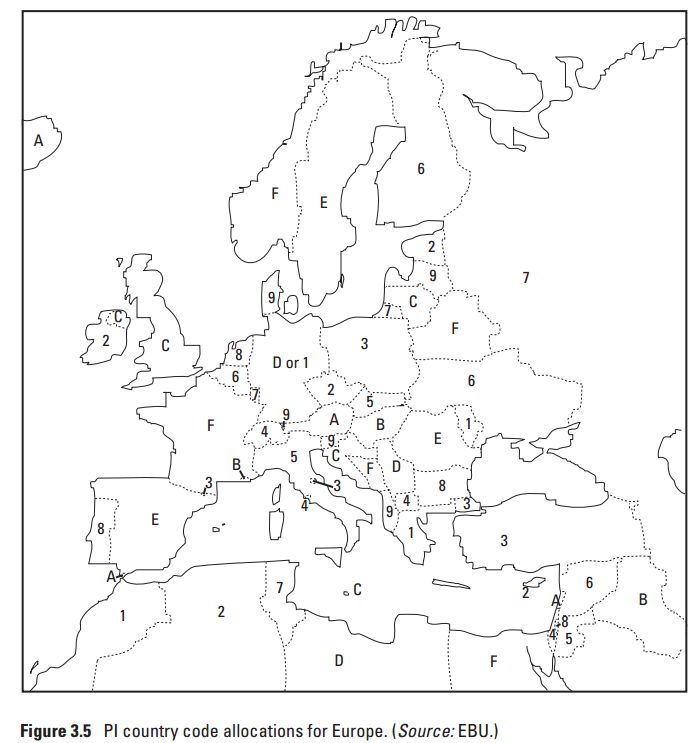
The Program Identification Code (PI, in all broadcast GT) is an internal transmitter identification code that is used , among other things, to search for AFs (alternative frequencies). It consists of a 16-bit number that enables the sender to be uniquely identified. The four-digit identification number contains a country code, a region identifier (Reg bit) and an individual numbering associated with the transmitter chain.
Extended Country Code
The PI codes are not unique. Even in Europe it can happen that they are used several times.
Example: Germany, Serbia and Libya all start with hex "D".
The Extended Country Code (ECC) together with the CI code uniquely identifies the country. Some countries, such as the USA or China, have several ECC + CI combinations. It is mainly used for TMC (Location Code Tables) and RadioDNS.
Radio text
Radio Text (RT, GT 2A, 2B) transmits additional information such as the current music title and artist or contact details of the station. The text is transmitted line by line, a line contains a maximum of 64 characters. In most car radios, however, this function is deliberately omitted for safety reasons so as not to draw the driver's attention to the text displayed. Radiotext and Radiotext plus (RT +) have now also been integrated into the current RDS specification EN 62106. At the same time, the number of implementations is increasing. a. even with "original radios" (so-called OEMs), which are firmly integrated in more modern vehicles.
Enhanced Radio Text
Enhanced Radio Text (eRT, GT = ODA) transmits additional information similar to radio text. The text is transmitted line by line, a line contains a maximum of 128 bytes, but a maximum of 64 characters. The coding is optionally in UCS-2 or UTF-8 , thus all characters worldwide are covered, including Chinese, Japanese, Arabic etc. The direction of writing (e.g. Arabic rl - Latin lr) is signaled in the transmission. Modern car radios can switch between RT and eRT, but the two radio texts must not be transmitted in parallel. In the current RDS specification EN 62106, Radiotext and Radiotext plus (RT +) have now also been integrated, which, depending on the implementation, can also be used on eRT.
Music / Speech
With Music / Speech (MS, GT 0A / 0B, 15B) is in a bit can distinguish between music and voice transmission, so that a radio, for example, between two sound profiles switch. Is now obsolete.
Clock time
The clock time signal (CT, GT 4A) is used for time synchronization. When the signal is broadcast, inaccuracies in the clock in the receiver can be corrected with this signal. This function is mainly used by the public broadcasters.
Open data applications
Open Data Applications (ODA, GT 5A, 6A, 7A, 8A, 9A, 11A, 12A, 13A + 1B, 3B, 4B, 5B, 6B, 7B, 8B, 9B, 10B, 11B, 12B, 13B) was introduced, in order to make the RDS system easily expandable and thus to be able to implement additional data services quickly without having to explicitly adapt the standard. Examples of ODAs are (in addition to the TMC mentioned above) the transmission of DGPS correction data; RT + (Radiotext plus), a machine-readable further development of Radiotext; or "iTunes Tagging", which enables a broadcasted piece of music to be identified in the iTunes Music Store (currently only HD Radio ).
RDS2 offers a further 64 ODA channels on three higher carriers. These are used with C-type groups.
Technical basics RDS

The data bits are transmitted at a data rate of 1187.5 bits per second. A digital double sideband method (2- PSK ) is used as the modulation method, with the ARI pilot tone of 57 kHz rotated by 90 ° being used as the carrier . Due to the 90 ° phase rotation, the ARI signal and the RDS signal can be received independently of one another, since these two signals are orthogonal to one another. In addition, the carrier is suppressed. The relationship between carrier and transmission rate is: carrier frequency (57 kHz) / 48. The prerequisite for independent reception is coherent demodulation . The phase information required for this is derived from the phase position of the stereo pilot tone at 19 kHz (⅓ of the RDS carrier frequency) in the receiver.
Technical basics RDS2
RDS2 knows up to three other carriers on the frequencies 66.5 kHz, 71.25 kHz and 75 kHz.

Modulation and transmission rates are identical for all streams. The groups are synchronized with each other on all four carriers.
With RDS, each 26 bits form a block, which in turn consists of 16 data bits and 10 check bits. A linear code is used here, which has a minimum Hamming distance of 5, which means that two random errors within a block can be corrected. The code is designed so that up to eleven further errors can be corrected if they are present as a bundle fault, i.e. directly next to one another. The block boundaries and the type of block can also be detected with the aid of the check bits. Four blocks (ABCD or ABC'D) each form an RDS group. RDS2 C-type groups only know ABCD blocks.
The synchronization of the blocks is also important. Data transmissions are normally always synchronized with the aid of a special data word, which has a high probability of being recognized in a noisy signal. However, this method cannot be used here because there is a continuous stream of data. A different method is used for this purpose: If one takes a closer look at the error correction method specified above, one finds that, in addition to the error corrections specified, there are other error possibilities that cannot be used because they do not fit into any scheme. From these unusable error words 5 are selected and assigned to the blocks. Blocks are A, B, C, D and C '. These errors are added according to the blocks on the sending side. Since the type of error can be detected on the receiving end, a recipient searches for these errors. If 3 errors can be detected in the correct group sequence, a correct synchronization can be assumed and the data can then be evaluated. Appropriate strategies for positive and negative bit slip still have to be developed on the receiver side, however.

The specifications can be found in the DIN standard DIN EN 62106.
The 16-bit sender ID (Program Identification, PI) is always transmitted in block A. In block B you can find the program type (PTY), an indicator for traffic information (TP) and the RDS group number (Group Type GT). This provides information about the use of the remaining five bits of block B and the 32 bits of block C and D. There are a number of RDS groups that are used for various additional data services, for example group 11A (see sample bit pattern) or group 3A for Open Data Applications (ODA).

RDS2 C-Type groups do not have a PI code. They consist of 1 byte header and 7 byte data. If the header is 0x0000, the remaining 7 bit are A or B type groups (tunneling), the PI code for this is taken from stream 0.

Control of the RDS broadcast
As long as the use of RDS is largely limited to the transmission of static data such as TP / TA or AF, control via acoustic signals (tones, such as Hinz trills ) is possible. For this purpose, the procedure “Control of the RDS / VRF system using the Hinz trill” was specified by the Deutsche Telekom in the letter FTZ 175 AB 33. Only a few devices were approved for control (including Rudolph HT090). If other services are to be used in addition, transmission to the RDS encoder in other ways is required (e.g. a separate data line). A suitable procedure can be found under UECP .
External RDS decoder
In principle, the RDS information can be taken from the audio signal of an FM radio. However, with many devices that are only designed for mono operation, all signals above the audible range are suppressed with a low-pass filter because they can have an unfavorable effect on the audio frequency amplifier, so that an RDS decoder does not work at the audio output of these devices.
Radio data systems
The RDS method can only be used in the form described for radio broadcasting in the VHF range. By means of phase modulation of the carrier, radio transmitters in the long, medium and short wave range can also transmit additional information that is not perceptible to the listener ( amplitude-modulated data system , AMDS).
See also
- Traffic Message Channel (TMC)
- Radio Aided Satellite Navigation Technique (RASANT)
- System for Wireless Infotainment Forwarding and Teledistribution (SWIFT)
Web links
- http://www.rds.org.uk/
- http://www.redesmadrid.com/rds/ RDS Decoder Spanish
- http://www.ukwtv.de/cms/downloads-aside/186-rds-software.html List of RDS decoder programs
- http://www.radioscanner.ru/uploader/2016/pi_codes_europe.jpg European PI code start nibbles
Individual evidence
- ↑ DIN EN 62106 correction 1 . Beuth Verlag website . Retrieved February 5, 2011.
- ^ RDS forum
- ↑ RDS groups list (Engl.)
- ↑ Dietmar Kopitz: Progress on theRadioTextPlus (RT +) implementation. (PDF 491.8 KB) RDS Forum Office, accessed on February 26, 2011 (English).
- ↑ DIN EN 62106: Specification of the Radio Data System (RDS), German version 2002, Beuth Verlag GmbH, Berlin