
Continuous miner

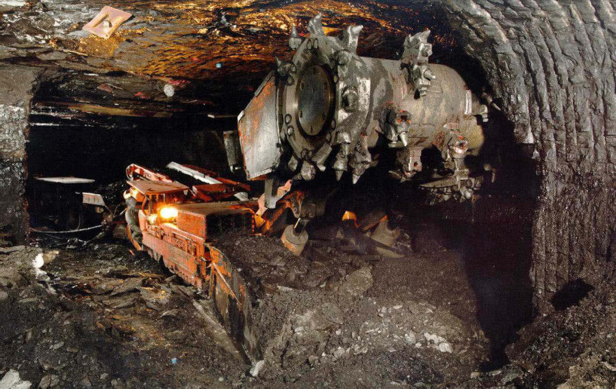
A continuous miner is a mining machine , which in the mining underground for recovering halite , gypsum and coal is used. Due to its design, the Continuous Miner is one of the circumferential milling machines. Continuous miners come in different sizes. Continuous miners are suitable for a working face with a small cross-section.
history
The first forerunner of a continuous miner was already in use in the second half of the 19th century. It was a machine powered by compressed air to drive a tunnel under the English Channel . The project was abandoned, however.
The first successful use of a continuous miner took place in 1943; the machine was built by the American Harold Silber. Joy acquired the patent for this continuous miner. In 1958, the first continuous miner was used in South African coal mining. The first continuous miners were used in Europe in the 1960s. In France, Great Britain and occasionally in Germany, these machines were used in seam tunneling . At the Niederrhein mine , a continuous miner achieved an average drive throughput of 23 meters per day. In 1966, continuous miners with eight cutting chains were used at the General Blumenthal colliery to excavate several seams. In the 1970s, a continuous miner on Prosper-Haniel achieved a daily drive-up capacity of up to 30 meters.
The continuous miners could not establish themselves in the European mountain areas and were displaced by roadheaders . This was due in particular to the high mountain pressure of the European mines caused by the great depths , but also to the fact that only one cross-sectional shape can be created with continuous miners. Continuous miners were increasingly used in South African mining. It wasn't until the early 1990s that continuous miners were used again in European mining.
construction
Each continuous miner consists of a base frame in which the machine's hydraulics are located. A caterpillar drive is located on each side of the base frame as a drive . The crawler track is driven electromechanically. A boom movable in the vertical direction is screwed to the chassis. The boom is driven hydraulically. The cutting tools are located at the upper end of the boom. Earlier machines used cutting chains arranged parallel to one another as cutting tools. Chisel-tipped cutting rollers are used in modern machines. The cutting tools are driven electromechanically. For the electrical supply of the continuous miner is with an approximately 250 meter long tow rope to the electricity network of the mine connected.
Types
Different types of continuous miners have been developed over the years; they differ mainly in the shape and type of cutting tools. There are the following types:
- Ripper type
- Borer Type
- Auger type
- Horizontal cutting head type
Ripper type

In this type of continuous miner, the cutting device consists of five or more vertically arranged cutting chains . The cutting chains are arranged close together. The cutter head can be moved vertically and horizontally. The boom is 1.5 meters wide and is moved hydraulically. Machines of this type can also cut mild rock with a compressive strength below 300 kg / cm 2 . Advantages of this type are the flexibility and the good adaptation to different mining conditions. The disadvantage is its low rate of degradation, due to the small attack surface of the cutting chains and its complexity. There were also ripper miners with an oscillating head. With this continuous miner, the base frame was initially mounted on rubber tires, but this construction was soon changed and replaced by crawler tracks. The swing head ripper had rotating cutting wheels that moved horizontally back and forth. However, the type could not prevail because the oscillating head was very maintenance-intensive.
Borer Type
In this continuous miner, the cutting device consists of two different parts. The main cutting element is the rotating cutting head to which cutting bits are attached. The cutting head has a diameter of 2.4 meters. The cutting head, also known as the cutting disk, is firmly connected to the machine and can therefore neither be swiveled vertically nor horizontally. There are machines of this type that are equipped with two or four cutting heads. The cutting heads are connected to each other synchronously. Each cutting head is connected to the machine with three arms. So that the machine can be moved, the arms can be adjusted so that the diameter of each cutting head can be reduced to 1.92 meters. The cutting heads cut a first shape into the mineral to be machined. In order to cut away the material remaining between the cutting heads, the machine is equipped with two horizontally arranged cutting rollers. These cutting rollers are equipped with chisels and rotate at 64 revolutions per minute. Machines with four cutting heads are equipped with cutting chains for this purpose. Side-mounted cutting chains are used to widen the profile.
The machines can cut adjacent rocks with a compressive strength of up to 300 kg / cm 2 . Larger machines of this type were developed by Marietta, Goodman and Joy. The Marietta Miner Type 675 weighed 57 tons and had an installed output of around 330 kilowatts. The excavation cross-section for smaller machines was up to 6.24 m 2 . Larger excavation cross-sections could be cut with larger machines with two or four rotors. Machines with two rotors were able to create excavation cross-sections of up to ten square meters. For machines with four rotors, the excavation cross-section was 18 square meters. The construction of the Marietta Miner was similar to today's full headers . Due to the lack of flexibility in use, fewer and fewer types of Borer have been used since the 1970s.
Auger type
This continuous miner has either two or four cutting heads ; each of these cutting heads has a diameter of about one meter. The wheels are driven by a motor located between the wheels. Each of the wheels can be moved from side to side, creating oscillating movements. As a result, several cuts are made in the face when the machine is advanced. The machine was mainly used to drive test tracks for so-called English longwall panels .
Types with rotating cutting head

These continuous miners are equipped with a cross-cutting head, which consists of a cylindrical support body to which the chisels are attached. Classic round shank chisels or disc chisels are used as chisels. Depending on the machine, the cutting head has a width of over seven meters and a diameter of 1.2 meters. The cutting head is attached to a boom. The boom can be pivoted vertically and can therefore move the cutting head up and down. However, the boom is usually not telescopic. The cutting head is driven by electric motors; There are two variants: In the first variant, the electric motor is located in the cutting head and drives the cutting head directly. In the second variant, the electric motor is located in the chassis and drives the cutting head via a chain.
The motor of each cutting roller has a cutting power of up to 400 kilowatts , depending on the size of the machine . So that the telescopic arm can be moved, it is connected to the miner's chassis via hydraulic cylinders. So that the machine does not make any nodding movements when the cutting roller is cutting, it is pressed against the sole in the rear area with a support cylinder . A loading table with side guide plates is located in the front area so that the recovered material can be conveyed away. In the middle of the loading table is a small chain conveyor integrated with the material to the distance conveyor is passed. Continuous miners with cross-cutting heads are offered by several companies. The machines are built for thicknesses between one and five meters. There are also different diameters for the cutting rollers.
Working method
The mining of the minerals by means of continuous miners takes place in several steps. The cutting roller must be guided vertically over the face. First, a cut is made in the face with the cutting roller. This is done with the rotating roller and the boom raised by moving the machine forward. The cut is made in the face up to the middle of the cutting drum. The rotating roller is then lowered down to the horizontal and the lower part of the mineral is cut out. The top pending part of the mineral is cut out in a similar way. The lower and upper edges must be trimmed with a cleaning cut. The extracted mineral is picked up by the loading table. To do this, the miner is moved forward and the debris is picked up from under the load table. The now picked up mineral is conveyed to the rear end of the miner by the chain conveyor. There it is either carried away with mobile chain conveyors or belt conveyors. Other options for funding are trackless vehicles such. B. sliding box vehicles such as shuttle cars .
commitment
Continuous miners are mainly used in American hard coal mining in mechanical extraction in local mining . In German hard coal mining, they were used to excavate seams. The best results can be achieved with continuous miners in hard coal and soft adjacent rock. The minerals to be worked with a continuous miner must only be slightly abrasive. However, the machines are not suitable for hard back rocks. Due to their design, they can only cut rectangular cross-sections , which is why they can only be used to a limited extent when driving on the road . Continuous miners can also be used to create longwall miners. They were also used to lower swollen beds . Continuous miners are also used in German salt mining , potash mining , for the extraction of natural soda and for the extraction of gypsum .
Productivity and costs
The productivity of mining operations with continuous miners is not significantly lower than the productivity of roller or planer operators . Comparing American collieries was the best operated with continuous miners pit before the best pit in the longwall was operated. The investment costs for a continuous miner operation were just under twelve percent of the investment costs that would have to be provided for longwall equipment. Thus, the investment costs that have to be raised for longwall equipment with approximately the same productivity are eight times as high as the investment costs for a company that is operated using the room-and-pillar method (chamber pillar construction). There is also used equipment for room-and-pillar operations, which is much cheaper to get than new equipment.
literature
- Howard L. Hartman et al. (Ed.): SME mining engineering handbook. Volume 1. 2nd edition. Society for Mining, Metallurgy and Exploration, Littleton CO 1992, ISBN 0-87335-100-2 .
Individual evidence
- ↑ a b c d e f g h i j k l m n o p q r Eric Drüppel: Development of a concept for the cutting extraction in rock salt . Dissertation 2010, Rheinisch-Westfälische Technische Hochschule Aachen
- ↑ a b c d M. Dubois: Driving up rocky stretches, state of the art in mid-1968 and outlook. In: Commission of the European Communities (Ed.): Research books coal, Heft 31, Brussels 1970, pp. 23–31.
- ↑ a b c d Illawarra Coal: TECHNOLOGY-The history of mechanization (accessed August 15, 2011)
- ↑ CONTINUOUS MINER SPRAY CONS IDERATIONS FOR OPTIMIZING SCRUBBER PERFORMANCE IN EXHAUST VENTILATION SYSTEMS (accessed March 18, 2016).
- ↑ a b c d JD Inch, JD Stone, ID Brumby, CJ Beukes: The use of continuous miners in South African coal mines Online (accessed August 15, 2011; PDF; 1.4 MB)
- ^ A b c Carl Hellmut Fritzsche : Textbook of mining science. Second volume, 10th edition, Springer Verlag, Berlin 1962.
- ↑ a b c Commission of the European Communities (ed.): Tunneling technology in the hard coal mining of the European Community. Verlag Glückauf GmbH, Luxembourg 1984, ISBN 3-7739-0440-1 .
- ↑ Manfred Bernauer, Blumenthal / Haard mine (ed.): Chronicle General Blumenthal. 4th edition. Vocational training BW Blumenthal / Haard, Recklinghausen 2009, p. 98.
- ↑ a b 40 years of technical development at RAG. In: coal. The employee magazine of the RAG Aktiengesellschaft , extra edition, Verlag Hoffmann und Campe GmbH, Neefs & Stumme (Wittingen), Herne 2008, pp. 14–15.
- ^ A b Ernst-Ulrich Reuther: Textbook of mining science. First volume, 12th edition, VGE Verlag GmbH, Essen 2010, ISBN 978-3-86797-076-1 .
- ^ A b c d e f g Heinrich Otto Buja: Engineering handbook mining technology, deposits and extraction technology. 1st edition, Beuth Verlag GmbH Berlin-Vienna-Zurich, Berlin 2013, ISBN 978-3-410-22618-5 .
- ↑ a b c d e f Heinz M. Hiersig (Ed.): VDI-Lexikon Maschinenbau. VDI-Verlag GmbH, Düsseldorf 1995, ISBN 3-540-62133-4 .
- ↑ a b c L. Gebhardt, M. Mitze, J. Reichel: Shear inflammable hydraulic fluids. In: Commission of the European Communities (Ed.): Forschungshefte coal, Heft 54, Luxemburg 1974, pp. 62–64.
- ^ A b c Walter Bischoff , Heinz Bramann, Westfälische Berggewerkschaftskasse Bochum: The small mining dictionary. 7th edition, Verlag Glückauf GmbH, Essen 1988, ISBN 3-7739-0501-7
- ^ A b Carl Hellmut Fritzsche: Textbook of mining science. First volume, 10th edition, Springer Verlag, Berlin 1961.
- ↑ a b c Commission of the European Coal and Steel Community (ed.): Trial with a "Continuous Miner" Marietta 780 A. August 1973, Contract No. 6210-08 / 3/311.
- ↑ a b c d Maxim Vorona: Optimization of the cutting process and prognosis of the relevant work parameters in the destruction of rock, taking into account the bit wear . Dissertation 2012, Technical University Bergakademie Freiberg.
- ↑ Gerd Bohnenberger: The cutting extraction at the Südwestdeutsche Salzwerke AG . In: Kaliverein eV (Ed.): Kali und Steinsalz, No. 02, Lippert printing house, Berlin 2007, ISSN 1614-1210 , pp. 30-37
- ^ Karl Nienhaus: Longwall and Örterbau - competition and supplement. In: Glückauf 136, trade journal for raw materials, mining and energy. No. 6, VGE Verlag Essen, Essen 2000, ISSN 0340-7896 .
Web links
- Photo: Continuous Miner in action (accessed August 15, 2011)