
D-Sub

D-Sub , as an abbreviation for English D-Subminiature , is a widespread design of a connector system , which has applications in the field of computer systems and data processing, among other things. This connector system is defined internationally in IEC 807-2. Depending on the application and country, this connector system is specified in various more extensive standards due to its widespread use, for example in the US military standard MIL-C-24308 or in Germany in the DIN standard 41652-1. Individual variants such as ISO 4903 for DA-15 and ISO 2110 for DB-25 are defined within the framework of ISO standards .
history
The US company Cannon (now part of ITT Corporation ) developed in 1952 a trapezoid- shaped connector type, and called his name because of the D-like shape of the external connector and because of the very small for that time design "D subminiature". This connector type was incorporated into the world of standards relatively quickly, especially in the MIL standard 24308.
Through the many years of use, the most diverse abbreviations of this "D shaped subminiature" connector have established themselves on the market, e. B. D Sub, D-Sub, DSUB, Sub-D, SUB-MIN-D, DE9 (D-Sub 9-pin), DB25 (D-Sub 25-pin), HD15 (D-Sub 15-pin high Density), HP50 (D-Sub 50-pin half pitch) and so on. In laboratory jargon it is still referred to today as a “Cannon connector ”, but in the audio and stage area it is understood to be the XLR connector, also developed by Cannon .
to form
Typical versions of the D-Sub type are:
- 2 rows 9-pin, without screws, for digital joysticks , paddles or light pens
- 2-row 9-pin or 25-pin as serial interface RS-232 (more precisely EIA-232) or V.24
- 2-row 15-pin as a game port , especially for analog joysticks, previously also paddles, etc.
- 2-row 15-pin for Apple monitor connection, e.g. B. Macintosh LC and LC II
- 2-row 15-pin with lock (network AUI )
- 2-row 19-pin for Atari DMA port ("ACSI"), Apple floppy connection "Smartport"
- 2-row 23-pin on Amiga computers for external floppy drives and monitor cables
- 2-row 25-pin as a parallel interface IEEE 1284 for printer
- 2-row 25-pin for SCSI- I and for digital TDIF -8-channel audio interfaces
- 3-row 15-pin for monitor cable ("HD15"), see VGA (connection)
- Closely spaced 50-pin SCSI ("HP50")
- With smaller pin spacing than higher density ( High Density , HD)
- With half the distance ( grid dimension 1.27 millimeters, half pitch )
- Combined with coaxial connectors, e.g. B. "13W3" (see VGA connection )
There are also a large number of special variants, such as a combination of high-current contacts with signal contacts or designs in which coaxial connectors , such as the "13W3" design, are integrated into the D-Sub connector housing. Because of their compact design, these designs are used, among other things, in the field of avionics and military technology. In the case of personal computers , the ATX standard in version 2.2 from Intel specified the color scheme according to the type of interface.

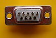
DB-25 connector from ITT-Cannon

13W3 connector

Special design with two high-current contacts and five signal contacts in the middle

DA-15 monitor connection on Apple - Macintosh LC


.jpg)
Sizes
| size | Normal density | High density | Double density | Distance between the holes for screw connection |
|||
|---|---|---|---|---|---|---|---|
| Surname | Pin arrangement | Surname | Pin arrangement | Surname | Pin arrangement | ||
| E. | DE-9 | 5 + 4 | DE-15 | 5 + 5 + 5 | DE-19 | 6 + 7 + 6 | 25.0 mm |
| A. | DA-15 | 8 + 7 | DA-26 | 9 + 9 + 8 | DA-31 | 10 + 11 + 10 | 33.3 mm |
| B. | DB-19 | 10 + 9 | 38.9 mm | ||||
| B. | DB-23 | 12 + 11 | 44.3 mm | ||||
| B. | DB-25 | 13 + 12 | DB-44 | 15 + 15 + 14 | DB-52 | 17 + 18 + 17 | 47.0 mm |
| B. | DB-35 | 18 + 17 | 38.9 mm | ||||
| C. | DC-37 | 19 + 18 | DC-62 | 21 + 21 + 20 | DC-79 | 26 + 27 + 26 | 63.5 mm |
| D. | DD-50 | 17 + 16 + 17 | DD-78 | 20 + 19 + 20 + 19 | DD-100 | 26 + 25 + 24 + 25 | 61.1 mm |
| F. | DF-104 | 21 + 21 + 21 + 21 + 20 | 63.5 mm | ||||
Geometry of the pins
The pins for signal application have a diameter of 1 mm. The rows of pins are 2.84 mm apart, adjacent pins are 2.74 mm ± 0.1 mm for sizes A and E, and 2.77 mm ± 0.1 mm for the other sizes. The rows of pins are offset by half this distance. In the case of special designs such as D-Sub connectors with high-current contacts or with integrated coaxial connectors, other diameters and distances occur.
In the case of the "high-density" types, the distance between the rows of pins has been reduced to 2.41 mm and the pins next to one another to 1.98 mm. With “Double Density” the distances have been further reduced; The rows are only 1.90 mm apart, the pins 1.65 mm
Mechanical locking
The mechanical locking - it is not implemented on all plugs - is implemented via two screw connections on the side. The usual threads are either the metric M3 or an incompatible UNC 4-40 . For correct locking, the plug and socket must have the same thread type.
Numbering of the connections
With regard to the numbering of the individual contacts ( pins ), there are always mistakes, which is due to the fact that some use the soldering perspective as a basis, while others use the top view (plug side) of the finished connector.


polarity

To differentiate between polarity (or “gender”), the common terms male / male (plug pins) and female / female (sockets for holding the pins) are also used for D-Sub plugs and sockets . Most manufacturers either use the short form derived from the English, i.e. M and F or P and S for plug and socket . A type with the designation “D-SUB 9P” is for example a plug with nine contacts, a type with the designation “D-SUB 25S” is a socket with 25 contacts.
| plug | Rifle |
|---|---|
| male | Female |
| times | female |
| M. | F. |
| Plug | Socket |
| P | S. |
In the context of the sex of the respective D-sub type, there are so-called "gender changer" (Eng. "Gender converter", see gender changer ) which invert the gender, ie male adapt to female or vice versa. The same numbers are connected to one another, which is why the pins or sockets cannot simply be connected straight through, but instead a page change takes place in the internal structure.
Designs
D-Sub plugs and sockets are produced in different versions and are quick, cheap and universal to use. The following are common:
- Solder cup connections to which any cables can be soldered (universally applicable, pin assignment can also be changed)
- PCB assembly for assembly on printed circuit boards , such as PC motherboards and plug-in cards . Depending on the model and manufacturer, the dimensions on the circuit board differ, but on the connector they are identical and suitable.
- Insulation displacement contacts for the direct quick connection of ribbon cables . These are relatively expensive, since different blade contacts are required due to the different grid dimensions from the ribbon cable to the D-Sub connection.
- Crimp connection for vibration-proof connections

DE-9 (male) with numbering (view on mating side)

DE-9 (female) with numbering (view on mating side)
DE-9 (male) with numbering and solder cup connection (view on solder side)

DE-9 (male)
90 ° PCB mounting, blue-green for serial interface RS-232 / V.24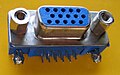
DE-15 (female) 90 ° PCB mount, blue for VGA connection

DB-25 (female) 90 ° - PCB mounting , raised, pink for LPT / parallel interface / printer connection IEEE 1284

DA-26 (male)

DC-37 (male) with insulation displacement contacts

DD-50 (male)
90 ° PCB mount
DE-2 (female / male) with two high current contacts

DF-104 (male)
90 ° PCB mount


Web links
Individual evidence
- ↑ IEC 807-2: Rectangular connectors for frequencies below 3 MHz. Part 2. Retrieved February 5, 2016 .
- ↑ MIL-C-24308c, Military Specification. Retrieved February 5, 2016 .
- ↑ a b DIN 41652-1: Plug connector for slide-in technology, trapezoidal, round contacts ∅ 1 mm; Common installation features and dimensions; Design overview (June 1990)
- ↑ CC Thomas: Amplimite Plug Assy, Size 1 thru 5, Series 109 with zinc plated shells. In: Farnell. TE Connectivity, May 17, 2005, p. 1 , accessed February 6, 2020 (English, data sheet).
- ↑ DF-104P D-subminiature connector pinout drawings . interfacebus.com. Retrieved July 24, 2014.
- ↑ Manufacturer's data sheet: D-Sub - Accessories for subminiature D connectors. (No longer available online.) Archived from the original on February 5, 2017 ; accessed on February 5, 2016 .