
Laser cutting
Laser cutting , also known as laser beam cutting , refers to the severing of solids by means of continuous or pulsed laser radiation through material ablation . Almost every type of material, for example metals, dielectrics and organic materials, can be cut with laser radiation according to the state of the art. The parameters of the laser radiation such as wavelength, average power, pulse energy and pulse duration must be adapted accordingly to the application. The microscopic removal mechanism and the thermal effects are essentially determined by the pulse duration and the irradiance.
The process is used where complex outlines (two- or three-dimensional), precise, fast processing (typically 10 m / min, but also up to over 100 m / min), the production of three-dimensional openings (even in poorly accessible places) and / and a contactless, almost force-free processing are required. Compared to alternative processes such as punching , laser cutting can be used economically even with very small batch sizes .
In order to combine the advantages of laser cutting with those of nibbling and punching, the manufacturers also offer combined machines that enable operations with the punching head as well as laser cutting of any contours.
Focused high-power lasers are used, mostly the CO 2 laser (a gas laser ) or increasingly Nd: YAG lasers ( solid-state lasers ) as well as the more efficient, easily focusable fiber lasers .
Components and structure

Important elements of a laser beam cutting machine are the laser beam source, the laser beam guide and the processing head (focusing optics) including the cutting nozzle. The beam leaving the laser beam source can be guided in the near infrared ( Nd: YAG laser , fiber laser , disk laser ) via fiber optic cable, with the CO 2 laser via deflection mirror to the focusing optics at the processing point. The focusing optics bundle the laser beam in a focus and thus generate the intensity required for cutting .
Systems with CO 2 lasers usually consist of a fixed laser beam source and so-called flying optics. A reflector telescope ensures a constant raw beam diameter on the focusing lens over the entire processing area. This is necessary because the beam emerging from the laser has a fixed divergence . Different run lengths of the radiation for different processing positions would change the raw beam diameter on the lens without compensation by the reflecting telescope. Different f-numbers and intensities would be the result.
The beam guidance between the optical resonator (laser beam source) and the focusing optics is implemented by mirrors that may be water-cooled. The mirrors are gold- or molybdenum-coated and consist of monocrystalline silicon or pure copper . Laser radiation in a wavelength range of approx. 1 µm ( Nd: YAG laser , fiber laser , disk laser ), on the other hand, can also be guided over great distances with fiber optic cables .
In the case of linearly polarized laser beams, phase-rotating mirrors are arranged between the resonator and the telescope for a direction-independent cutting quality . A circularly polarized beam is usually generated from a linearly polarized beam. The mirrors used have a multilayer coating, the function of which is equivalent to a lambda / 4 plate . The often folded resonator structure of CO 2 lasers causes linear polarization and makes the use of a phase shifter necessary. The polarization-dependent absorption of laser radiation in the cutting gap would lead to a direction-dependent edge quality and cutting efficiency.
The focusing optics, also known as the processing head, consist of a special glass in Nd: YAG lasers and other lasers in the near-infrared range, and in carbon dioxide lasers from monocrystalline zinc selenide or an off-axis parabolic mirror made from copper.
The jet passes through the so-called cutting nozzle, which is usually made of copper and also directs the blowing or process gas onto the processing point.
Procedure


Thermal laser cutting consists of two sub-processes that run simultaneously. On the one hand, it is based on the fact that the focused laser beam is absorbed at the cutting front and thus brings in the energy required for cutting. On the other hand, the cutting nozzle, which is arranged concentrically to the laser, provides the process gas or blown gas that protects the focusing optics from vapors and splashes and continues to drive the removed material out of the kerf. Depending on the temperature reached in the effective range and the type of process gas supplied, different states of aggregation of the joint material arise . Depending on whether the material is removed from the kerf as a liquid, oxidation product or vapor, a distinction is made between the three variants laser beam fusion cutting , laser beam flame cutting and laser beam sublimation cutting .
Currently, the maximum workable thicknesses are for steel at about 40 mm, for stainless steel with 50 mm; Aluminum is cut up to about 25 mm with a laser. Compared to steel, it is technically more complex to cut aluminum or copper , for example , since most of the radiation introduced is initially reflected and therefore a much greater power or power flux density is required when piercing. Even if a greater proportion of power is absorbed in the cutting gap during cutting, the cutting power is much lower than with ferrous materials, since the thermal conductivity of aluminum and copper is much higher and no supporting oxidation is decisive.
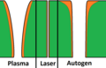
Cross-sections of the kerfs in plasma cutting, laser cutting and oxy-fuel cutting
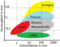
Accuracies for different sheet metal thicknesses: flame cutting, plasma cutting, water jet cutting, laser cutting and spark erosion (EDM)
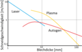
Cutting speeds for oxy-fuel cutting, laser cutting and plasma cutting

Laser cutting of copper with a solid-state laser machine


Copper and other metals with good thermal conductivity are difficult or impossible to cut with the CO 2 laser. However, this depends not only on the thermal conductivity, but rather on the fact that a very large proportion of the radiation introduced is reflected and the material is therefore hardly heated. However, pulsed Nd: YAG lasers can be used for thin sheet metal - all materials can be cut with these.
The most critical process in laser flame and fusion cutting is piercing. It is time-consuming as it is often necessary to work pulsed with a reduced average laser power in order to avoid back reflection and metal splashes that could endanger the focusing optics. Modern laser machines have sensors with which the puncture can be detected in order to save time and to ensure that the cut does not start before the material has been completely pierced.
When laser cutting steel, the cut edges become harder due to the high temperature differences. This can lead to problems in subsequent processing.
When cutting, flat material lies on a support (teeth, points, cutting edges) that must meet several conditions:
- Smallest possible contact surface - waste or small parts must fall through
- low back reflection - otherwise possible damage to the workpieces from below or to the laser beam source
- high resistance to laser beam ablation - long maintenance intervals
The procedures are classified as follows:
Laser beam fusion cutting
During fusion cutting, the kerf is formed by continuously melting and blowing out the cutting material with an inert or inert gas. The gas jet also prevents the surface from oxidizing. For reasons of cost, mainly nitrogen , less often argon or helium is used. The gas pressures can reach up to 22 bar (high pressure inert gas cutting). Due to the low degree of absorption of the material, the cutting speeds during fusion cutting are u. a. depending on the available laser power. A typical cutting speed of 1.1 m / min is achieved with a 5 kW CO 2 laser cutting system for 10 mm thick stainless steel 1.4301. The process is mostly used when oxide-free kerfs are required in stainless steels. Aluminum alloys and high-melting non - ferrous alloys are another application. Even normal structural steel is sometimes cut with nitrogen at thicknesses up to approx. 6 to 10 mm, since the cut edges then no longer have to be reworked for later painting or powder coating.
A high cut quality is characterized by the slight formation of scoring on the cut edges and the lack of burrs on the underside of the cut. The laser beam liquefies the material not only on the cutting front, but in a semicircle up to the cutting edges. Due to the continuous feed and the resulting melting of the material, the material can solidify on the cut edges. The solidification takes place in a wave-like manner, which concomitantly defines the characteristic groove structure or the roughness of the cut. A beard or burr formation is caused by insufficient driving forces of the gas flow, so that the melt cannot be driven out completely. Melt droplets on the lower edge of the cut can solidify and form a more or less strongly adhering beard / burr. The parameters that influence the quality of the cut include: a. the focus position, the feed speed, the laser power, the intensity distribution or the cutting gas pressure.
Laser cutting
The most common way of cutting ferrous metals in the past was flame cutting. Similar to oxy-fuel cutting , the material is heated to ignition temperature and burned by adding oxygen (blowing gas). The energy released during burning supports the cutting process considerably. The resulting iron oxide (slag) is blown out by the oxygen jet. In the case of some non-ferrous metals, the heat introduced by exothermic reactions is insufficient to significantly support the cutting process. Accordingly, only materials can be processed whose ignition temperature is below the melting temperature . Oxide layers remaining on the cut edges during laser flame cutting can impair further processing (e.g. welding ) or even powder coating or painting.
The main area of application is the processing of low-alloy and unalloyed steels and, in individual cases, stainless steels. CO 2 lasers are usually found here as the beam source. The cutting speeds are up to 250 m / min for sheets less than 1 mm thick and, for example, with a 4 kW CO 2 laser around 0.8 m / min for 20 mm thick structural steel.
Burr and scale buildup and the roughness of the cut surface are the essential technological and qualitative parameters. The width of the kerf is slightly larger than with the other two methods and is around 0.1 to 0.8 mm, depending on the sheet thickness. The formation of burrs can almost be avoided with laser beam cutting with suitable process parameters. In order to avoid burning off sharp contours and unclean puncture holes, the laser power must be turned down.
The blowing gas pressure (oxygen) is a few bar.
Laser beam sublimation cutting
Characteristic of sublimation cutting is the evaporation or pyrolysis of the heated material and the immediate blowing out of the vapors. Materials without a pronounced molten state are the main area of activity of sublimation cutting; these can be inorganic as well as organic substances. The transition of the material from the solid to the gaseous state takes place here directly ( sublimation ), i.e. without being liquid in between. The process gas not only blows the steam out of the kerf, but also prevents it from condensing in the kerf. Typical materials are, for example, wood, leather, textiles, homogeneous and fiber-reinforced plastics.
In principle, sublimation cuts are free of burrs. The resulting gases are often flammable. Air or nitrogen is usually used as the blowing gas. The darkening of the cut edges on wood can be reduced by pulsing, using oxygen-containing blowing gas (air), good focusing or fast cutting with sufficient power.
PMMA can be processed burr-free with transparent, smooth cut edges.
With pulsed lasers with high peak power and high power flux density, materials that normally do not sublime can also be ablated almost free of a melt or heat-affected zone.
Further procedures
Other laser beam-induced cutting processes are scribing and so-called thermal laser beam separation (TLS).
In scoring, one of the earliest laser processes, a scoring track is made in brittle materials (notch or row of blind holes), which can then be mechanically broken along. Typical materials are solid state disks, thick film - and resistance - ceramic substrates and glass.
With TLS, thermal stresses are created along a line, which leads to a continuous thermally induced break. The prerequisite is that there is a scratch at the beginning. Not all shapes can be made this way. There is no melting and no material removal. Brittle materials such as semiconductor wafers, ceramics and glass are suitable.
Advantages and disadvantages compared to conventional methods
- advantages
- low minimum quantities from 1 piece, high flexibility
- Depending on the system, all materials can be cut
- high material utilization, economical
- Depending on the material, clean, narrow, often rework-free cut edges
- Engraving / marking and cutting is often possible with the same beam source and in the same operation
- disadvantage
- high system costs
- Occupational safety (see below)
- depending on the laser beam source, high use of electrical energy
- Gas consumption (blowing and process gas as well as gases for gas lasers, especially the expensive helium)
Pollutants and occupational safety
Invisible laser radiation is used in laser cutting. The power is so high that scattered and reflected beam components can lead to skin and eye damage.
Laser machines therefore usually have a closed cabin that can only be opened when the laser beam is switched off. The danger of (mostly undetected) eye damage exists especially with Nd: YAG lasers.
The beam resistance of the housing becomes a problem with increasing laser power and especially with the large focal distances of the fiber laser (remote cutting). Even thick concrete slabs are often penetrated in a few seconds. The trend is therefore towards so-called active housings, which recognize the impact of a laser beam or the beginning of destruction and switch off the laser.
With metals, the material of the kerf occurs as an aerosol . The cutting of structural steel is usually seen as less problematic, whereas the alloy components ( cobalt , nickel , chromium , etc.) appear in high-alloy steels . However, cutting beryllium copper is extremely dangerous .
During laser cutting, organic materials are broken down into chemical substances that are often hazardous to health by pyrolysis . The cutting of organic materials containing halogens such as PVC or PTFE , or materials with flame retardants , is particularly problematic.This results in highly toxic dioxins and furans as well as highly corrosive gases ( chlorine , hydrogen fluoride ).
Flammable gases and the laser beam itself create a fire hazard.
Depending on the material, laser cutting produces smoke, which leads to undesirable discoloration or deposits on the cut edge. In order to avoid time-consuming reworking, this smoke must be evacuated as it is being created. This must be done directly at the cutting gap not only because of process reliability, but also for reasons of work and environmental protection.
The exhaust air from laser beam cutting systems passes through filter systems protected against fire (particle filters, carbon filters).
Work preparation

CAD / CAM systems are predominantly used for offline programming of the two or three-dimensional (2D or 3D) cutting contours. The processing (contour recording, cutting sequence, material-saving arrangement by nesting , cutting gap correction, or post processing for short ) of the geometric data created with a CAD system is often done directly on the machine control. Complex three-dimensional cutting contours are often created, corrected or completed by teach-in on the machine. The software used for work preparation sometimes also allows the cutting length, the processing time and the required material and media quantities to be determined.
See also
literature
- Helmut Hügel, Thomas Graf: Lasers in Manufacturing - Beam Sources, Systems, Manufacturing Processes , Vieweg Teubner, 2nd edition, 2009.
- Anika Kehrer, Teja Philipp, Sven Rens: Lasercutting - Create, cut and engrave your own designs , Hanser Fachbuch, 1st edition, 2017. ( Book page from the publisher ) (Note: Theoretical introduction applies to all lasers, but the practical focus is on diode lasers on the grounds that it scales for creative home use)
Individual evidence
- ↑ Reinhart Poprawe: Tailored Light 2: Laser Application Technology . Springer Science & Business Media, 2011, ISBN 978-3-642-01237-2 ( google.de [accessed on October 9, 2016]).
- ↑ Annual report of the Fraunhofer Institute for Laser Technology ILT 2008 (PDF; 5.6 MB) High-speed cutting of automotive steels using a fiber laser , p. 67 (English).
- ↑ A force is created by the recoil of the expelled material and by the blowing / process gas
- ↑ Annual report of the Fraunhofer Institute for Laser Technology ILT 2005 (PDF; 2.7 MB) Fusion cutting with a 5 kW fiber laser , p. 70 (English).
- ↑ http://www.freepatentsonline.com/EP0655021.html Patent specification laser cutting nozzle
- ↑ Power consumption is significantly higher than with punching, but lower than with plasma cutting.
Web links
- Video clips on the laser cutting of sheet metal with information on the cutting processes used
- HTWK Leipzig Finishing Lexicon: Laser cutting
- Process video of the combined machining of laser cutting and welding with one machining head
- Process video of the combined machining of laser cutting and welding with one machining head