
Suspension

yellow parts: lower and upper wishbones connected by the connecting part of the steering knuckle
The wheel suspension or wheel guide is the moving connection between the vehicle body and the wheels. It contains guide elements that guide the wheels on predetermined, almost vertical paths with respect to the vehicle body.
Types of construction are: rigid axles , independent wheel suspensions (adjacent illustration) and compound axles.
The components of the wheel suspension are part of the chassis of a vehicle .
The design of the wheel suspension is an essential part of vehicle technology .
By suitable design of the Radführungsgeometrie and the suspension , it is possible undesirable side effects of between vehicle body and wheels to transfer wheel loads and dynamic forces (driving, braking, and side forces), such as pitch and Wank mitigate motions of the vehicle body. The self-steering behavior can be positively influenced ( sub - instead oversteer ).
General
The wheel suspensions are intended to ensure safe driving behavior and to reduce the loss of driving comfort due to uneven road surfaces (let the vehicle body vibrate and dampen the transmission of noise). To do this, they must:
- the wheels in case of impacts elastically yielding ( suspension ) lead to change noticeably, without the suspension geometry and thereby have a very long travel,
- Dampen vibrations ,
- Forward steering movements,
- be as light as possible ( small unsprung mass )
Since the requirements sometimes contradict each other, the design and coordination are always a compromise.
The wheel suspension includes: wheel carriers (steering knuckle or continuous axle beam), control arms and joints . For the springs and shock absorbers that are always involved: see suspension (vehicle) .
Degree of freedom of the wheel guides
An individually suspended wheel should be guided spatially or for example at the free end of a rocker on a curved circular arc according to a defined law . The degree of freedom of such a movement is f = 1.
The axle bridge of a rigid axle should be both vertically displaceable (or rotatable around the vehicle's transverse axis) and rotatable around the longitudinal axis so that the wheels attached to their ends can deflect independently of one another:
- If both wheels could only deflect in the same direction and with the same stroke at the same time, this would be a "stroke suspension" or "parallel suspension".
- If both wheels could only deflect at the same time, but in opposite directions with the same stroke, this would be "roll suspension".
The degree of freedom of the rigid axle guide is f = 2. This can be symbolized by a swivel joint in the center .
Designs
The different designs of the wheel guide do not differ in principle whether the wheels are steered or not.
The scope for interpretation is limited when the guided wheels are driven.
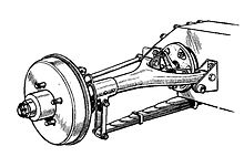
Rigid axle
“The term wheel suspension has only been in use in automobile construction since the [19] 30s ... In the past, we spoke of axles. This term was only introduced with independent suspension. (In the meantime) one uses (it) also for rigid axles as a possible form. "
In the case of a rigid axle, the wheel carriers of an axle are connected to one another via a rigid axle beam ( "axle bridge" ).
The axle bridge is usually guided by leaf springs or combinations of links on the vehicle body and is sprung across from it. When guiding with a central ball joint in combination with a wishbone, the basic shape of the axle body is changed. Rigid axles with i. d. Usually integrated differential gear in roughly chronological order:
- Rigid axle with leaf springs: guidance exclusively by means of two longitudinally mounted leaf springs. One of the spring halves is articulated on the vehicle body and acts as a longitudinal rocker (transmission of the longitudinal forces; the second spring end slides longitudinally under the body = thrust bearing). The transversely stiff springs also transfer the transverse forces (exceptionally via a Panhard rod ). Torques during acceleration and braking turn the axle around itself and deform the leaf springs in an S-shape ("pulling up" the axle).
Example images: [1] , with Panhard stick: [2]
- Rigid axle with rod core: Four rod links are required for the kinematically determined guidance of a rigid axle. Two of these links can be combined to form a wishbone that takes over the lateral guidance. Kinematically overdetermined rigid axles by means of four trailing arms and Panhard rod or Watt linkage for lateral guidance are also common.
- Drawbar / thrust ball / central joint axle: A drawbar (or a "thrust tube") that is rigidly attached to the axle body and supported at its front end with a ball joint ("thrust ball", central joint) on the vehicle body is the "simplest type of longitudinal guidance and torque support around the Vehicle transverse axis “ Only the transverse guidance requires an additional link (Panhard rod or similar). Instead of being extended with a push tube, the axle beam can be curved towards the front as a De-Dion axle as in the Smart Fortwo [3] (axle bridge offset to the front with elastic central joint and wishbone / s, coil springs) or as a non-driven rigid axle as in the Fiat Panda . A variant with a central joint not fixed in the horizontal plane, but with two trailing arms, was available from Opel : [4] .
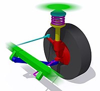
Independent suspension
With independent suspension, the two wheels on an axle (front or rear axle) are guided independently of each other. The wheel position of one wheel is independent of that of the other. The following chronological list also leads to a solution that improves the driving characteristics, but is incomplete:

1. (Swivel) sliding joint, Decauville , 1902

2. right of 2 sliding joints on the rear wheel, BMW R 51/2
3. Pendulum axle (broadly mounted cross arm) of a front-wheel drive Derby

4. Pendulum axle of the VW Beetle , transverse swing arms = chrome-plated tubes, torsionally soft trailing arm = "swords" (left trailing arm behind brown shock absorber)

5. 2 parallel handlebars that can be rotated around the transverse axis, VW Beetle / Formula Vee racing cars


.jpg)

.jpg)
- Decauville - (swivel) push joint for steerable front wheel: The push joint (column in sleeve) guides the wheel vertically against a leaf spring.
- 2 parallel sliding joints: straight travel suspension on the motorcycle, front ( telescopic fork ) and rear.
- Pendulum axle of a front-wheel drive Derby : 1 wide-mounted cross arm per wheel
- Swing axle of the rear-engined VW Beetle : the wheel 1 cross link (drive axle embracing tube) and 1 torsionally trailing arm ( "sword") image
- Crank handlebar axle of a VW Beetle / Formula Vee racing car on the front axle: 2 parallel trailing arms that can be rotated around the transverse axis , handlebars with one ball joint each connected to the wheel carrier, wheel pulled (VW) or pushed.
- Double wishbone suspension : 2 front (or rear) broadly mounted wishbones rotatable around the longitudinal axis ("triangular links"), tie rod.
- Trailing arm axle : swing arm on non-driven rear wheel, rotatable around transverse axis, wide bearings and rigidly dimensioned, Renault 4
- Trailing arm axle as a driven rear axle: inclined and wide-mounted swing arm (handlebar is incorrect because it is firmly connected to the wheel carrier)
- MacPherson suspension on the front wheel (less often on the rear wheel): 1 swivel arm and 1 wide-mounted wishbone ("triangular link"), tie rod.
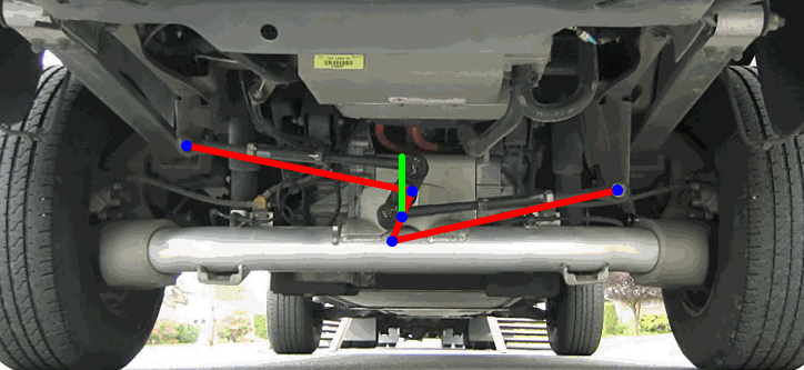
- Multi-link axle : The currently most complex designs of the wheel suspension use up to 5 simple rod links in order to achieve the most favorable driving characteristics in this way. The number of possible designs corresponds disproportionately to that of the number of drivers, so that a “clear property profile cannot be specified”. The example shown contains a "wishbone" (yellow) that has not yet been replaced by two simple links.

6. 2 wide mounted wishbones ("wishbones")

7. Swing arm on left rear wheel (not driven), Renault 4

8. Diagonal swing (incorrect: semi-trailing arm) on driven rear wheels
9. MacPherson suspension of a front wheel:
1 swivel arm , 1 wishbone below, tie rod
10. Rear multi-link axle with three single links and a "triangular wishbone " (yellow), Mitsubishi Galant EA0


![[1]](https://data.motor-talk.de/data/galleries/611436/5773986/ado28dev-07-64896.jpg)
![[2]](http://hondaoldies.de/Korbmacher-Archiv/Technik/panhardstab.jpg)
![[3]](http://adsves.weebly.com/uploads/2/1/8/2/21829402/121037_orig.jpg)
![[4]](http://www.kadett-c.eu/allerlei/12/HA344_d.jpg)
Composite suspensions: semi-rigid axles
Of the multitude of possible versions of composite suspensions, only the most common representatives at present, the so-called "semi-rigid axles ", are discussed below: This somewhat imprecise term includes the torsion crank axle and the twist beam axles as non-driven rear axles.
The common feature of these axle constructions are two parallel longitudinal swing arms, which are connected to one another by a rigid but torsionally flexible rod (usually with a T or U-shaped profile). Depending on the position of the composite rod, the behavior is more similar to a rigid axle or a trailing arm axle. Due to the flexural rigidity of the connection, the wheels remain approximately parallel in the case of roll suspension, despite the non-parallel oscillations (an advantage inherited from the rigid axle). The torsionally flexible connecting rod also acts as a stabilizer .
The twist beam axle (the coupling link axle is just a subspecies of it) is due to its simple concept (simple (welded) assembly with little space requirement plus two rubber bearings, no axle carrier required on the vehicle body, among other things) "the cheapest non-driven rear axle ever". The initially neglected tendency to oversteer due to the elastic rotation of the axle assembly around the vertical axis in the rubber mounts was later essentially eliminated with the track-correcting bearing specially developed for this purpose .
The connecting rod of the torsion crank axle (first on the DKW Junior , 1958) has a U-cross section (originally a slotted tube) and is guided on torsionally flexible rockers (swords) and a Panhard rod.
The twist beam axle appeared in 1974 as a rear suspension on the VW Scirocco and the Golf . At the widely spaced suspension points of the axle unit (pivot points of the swing arms) on the vehicle there are flexible rubber mounts ( track-correcting since 1988, Passat ).
Elastokinematics
When designing a wheel suspension, all the components involved can only be viewed as rigid bodies in a first step ( kinematics of the rigid body ). Handlebars and other “rigid” metallic components give in noticeably elastically - especially under forces and moments, the transmission of which is not their main task. The bearings are deliberately designed to be elastic in order to dampen shocks and sound: rubber bearings .
The elasticities lead to additional freedom of movement, which must be included in the design of a wheel suspension upon closer examination under the term elastokinematics . The aim is to "compensate for the inevitable deformations ... or even to convert them into desirable movements." B. achieved with the track-correcting bearing developed for the twist beam axle .
See also
literature
- Karl-Heinz Dietsche et al .: Automotive pocket book. Robert Bosch GmbH, 28th edition, Springer Verlag, Wiesbaden 2014, ISBN 978-3-658-038007 .
- Rolf Gscheidle: Expertise in automotive technology. 30th edition, Verlag Europa-Lehrmittel, Haan-Gruiten 2013, ISBN 978-3-8085-2240-0 .
- Bernd Hoting, Metin Ersoy, Stefan Gies: Chassis Manual . 4th edition, Springer Vieweg Verlag, Wiesbaden 2013, ISBN 978-3658019914 .
- Wolfgang Matschinsky: Wheel guides of road vehicles: kinematics, elasto-kinematics and construction , 3rd edition, Springer Verlag Berlin Heidelberg 2007, ISBN 978-3-540-71196-4
Individual evidence
- ^ A b Wolfgang Matschinsky: Wheel guides for road vehicles. , P. 1
-
^ A generic term introduced by W. Matschinsky as "composite suspensions" (cf. Wolfgang Matschinsky: p. 21): These include all designs that are not rigid axles or independent wheel suspensions and are characterized by
- that they spread like the rigid axle over the entire width of the vehicle,
- that the two wheels are not rigidly connected to each other, but cannot move independently of each other like individually suspended wheels.
- ↑ RWTH Aachen, Institute for Automotive Engineering: Explanation of the term "lift and roll suspension", page 15 . "Parallel suspension": cf. Matschinsky, page 442
- ↑ A "sliding block guide" is occasionally used in racing vehicles, cf. Matschinsky, p. 186, Figure 7.10.
- ↑ Erich Henker: Fahrwerktechnik , Vieweg, 1993, p. 103
- ↑ Wolfgang Matschinsky: Radführung der Straßenfahrzeuge , P. 18–21: Overview of the kinematic variants
- ^ Metin Ersoy, Stefan Gies (ed.): Chassis manual: Basics - Driving dynamics - Driving behavior - Components ... 5th edition. Springer Vieweg, 2017, ISBN 978-3-658-15467-7 . : ( limited preview in Google Book search)
- ^ Quote from Matschinsky, p. 422
- ^ Wolfgang Matschinsky: Radführung der Straßenfahrzeuge , P. 15-18: Overview of the kinematic variants
- ↑ In the literature, the treatment of the front wheel suspension occasionally includes the function of steering the vehicle. This is not the case here and below. The rotational component of the swivel joint is shown in brackets, and no reference is made to the tie rod and corresponding levers.
- ↑ a b Bernd Heißing, Metin Ersoy, Gies: Chassis Handbook , p 448th
- ↑ Bernd Heißing Metin Ersoy, Stefan Gies: Chassis Handbook , page 472: "torsion beam" and "Torsionskurbelachse" had together in 2005 and 2010 globally on all rear axles account for more than 30%.
- ↑ Bernd Heißing, Metin Ersoy, Stefan Gies: chassis manual . , P. 436.
- ↑ Karl-Heinz Dietsche et al .: Kraftfahrtechnisches Taschenbuch , p. 859.
- ↑ Bernd Heißing Metin Ersoy, Stefan Gies: Chassis Handbook , p 434
- ↑ Wolfgang Matschinsky: Wheel guides for road vehicles , Chapter 9
- ^ Quote from Wolfgang Matschinsky: Radführung der Straßenfahrzeuge , p. 287