
Kaplan turbine

The Kaplan turbine is an axial flow water turbine with an adjustable impeller and is used in hydropower plants . It was further developed and patented from the Francis turbine by the Austrian engineer Viktor Kaplan in 1913 . The cavitation , which occurs particularly easily with this type of turbine, repeatedly led to setbacks in the development work. The first Kaplan turbines could only go into successful continuous operation when they understood how to get this phenomenon under control by means of constructive measures on the turbine .
Working principle
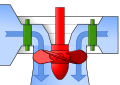
In the Kaplan turbine, the impeller resembles a ship's propeller , the blades of which are adjustable (see controllable pitch propeller ). The speed of a classic Kaplan turbine is constant regardless of the amount of water. The generator of a Kaplan turbine can therefore feed directly into the network with the appropriate gear ratio. By adjusting the blades of the propeller, it is achieved that the blades are always optimally flown around with fluctuating amounts of water and thus achieve a high level of efficiency. Turbines without this blade adjustment are called propeller turbines . In order to achieve a high degree of efficiency and high capacity with fluctuating water volumes, the speed of propeller turbines is adjusted (electrotechnical control): the same effect is achieved in terms of fluid mechanics as when adjusting the impeller blades of a classic Kaplan turbine. If the water volume is constant, there is no need to adjust the speed or adjust the impeller blades and feed them directly into the network.
The tail unit , also known as guide vanes, is located in front of the impeller . It ensures that the water hits the blades of the turbine optimally and sets the turbine in rotation. By adjusting the guide and impeller blades (double regulation), the efficiency of the Kaplan turbine can be adapted to different water volumes and head heights. The efficiency achieved is in the range of 80-95%.
Double-regulated turbines are ideally suited for use with low to very low heads and large and fluctuating flow rates. The Kaplan turbine is therefore predestined for large river power plants on calmly flowing large bodies of water, as well as for irrigation canals, residual hydroelectric power plants and use in mills.
The water pressure decreases steadily from the entry into the impeller to the exit - in the Kaplan turbine, potential energy is converted into kinetic energy. The residual energy is dissipated in the intake manifold, which is connected downstream of the turbine. The water leaves the turbine through the suction pipe and goes underwater.
Types
- Schemes of different variants of Kaplan turbines and Kaplan-like designs
vertical Kaplan turbine;
The generator is above the water inlet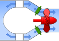
actual Kaplan bulb turbine;
The generator is inside the bulb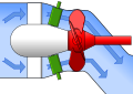
S-turbine;
The turbine shaft leads through the suction pipe to the generator
Gear bulb turbine;
The turbine shaft is connected to the generator via a gearbox
Straflo turbine;
the turbine blades carry a circumferential ring with the generator rotor
VLH turbine;
the generator is installed inside the impeller
DIVE turbine with fixed impeller blades;
The generator sits directly above the turbine and is completely flooded


Vertical Kaplan turbine

Kaplan turbines are usually installed vertically so that the water flows through from top to bottom. In the case of relatively high heads , a spiral is used in front of the turbine , which turns the water into a swirl . An inlet shaft or a simplified semi-spiral is sufficient for lower heads. The three-phase generator, designed as a salient pole machine, is usually attached directly above the turbine in order to be able to transfer the kinetic energy generated by the impeller to the generator rotor via a vertical shaft without deflection losses.
Bulb turbines
From the Kaplan turbine, the Kaplan bulb turbine was developed for low heads of up to 25 m and an output of up to 75 MW, the shaft of which is installed horizontally in the direction of the flowing water with an impeller . This avoids deflection losses and thus a greater absorption capacity and a higher full-load efficiency.
Classic bulb turbine

1 impeller blade, 2 guide vane, 3 guide vane control, 4 support vane, 5 turbine shaft, 6 generator, 7 manhole
The generator is located in a waterproof housing at the extended end of the turbine shaft. The horizontal arrangement means that less space is required and thus a lower construction height of the machine house , which means that the landscape is less impaired.
S turbine

|

|
|
|
Model of the S-turbine in the waterworks at Hochablass . The inlet of the turbine forms the funnel-shaped inlet with the conical tail unit . The mechanism for adjusting the guide vanes is marked in yellow. The impeller has adjustable blades.
|
||
One of the special forms of the Kaplan bulb turbine is the S turbine (for heads up to 15 m). The suction pipe is bent in an S-shape so that the turbine shaft can be guided out. The generator is installed outside the turbine and is therefore more easily accessible for regular checks and maintenance work. The overall height can thereby be reduced even further. This also makes it possible to install the turbines in small hydropower plants, for example over a narrow river or a canal , with a drop of up to 5 m or a slight damming through a weir . S turbines are used in power plants up to a capacity of 15 MW.
See also types of hydropower plants .
Gear bulb turbine
Another special form is the geared bulb turbine (for heights of up to 12 m). It is very similar to the S-turbine , but it differs in two essential features. The suction pipe is straight and the turbine shaft is connected to the generator via a gear instead of directly. This can be done horizontally or vertically, making the design even more compact compared to the S-type turbines . The speeds of the turbine and generator can be optimized separately by means of a suitable step-up or step- down. Geared bulb turbines are used in power plants with an output of up to 4 MW.
Straflo turbine
A further development of the Kaplan bulb turbines are the so-called Straflo turbines (of English. Flow straight , straight flow). In this type of turbine, the rotor of the turbine and the rotor of the generator form a unit that lie in a common plane . This means that the Straflo turbine does not have its own shaft ; instead, the turbine blades have a circumferential ring in which the excitation winding is integrated. In contrast, the stator winding is built into the housing of the turbine; it lies in the water that drives the turbine. The storage of the turbine axis is done on one side in a sealed housing. A technical challenge with this design is the external seal on the ring generator. Due to the centrifugal forces that act, there is a risk that sand will be carried into these seals and cause increased wear. Early versions of this arrangement were patented by Arno Fischer in 1936 and installed in the Maria Steinbach power plant , which was inaugurated in 1938. Today, modern Straflo turbines can be found, for example, in the Laufenburg run-of-river power plant and the Annapolis tidal power plant .
Kaplan-like designs
Usual vertical Kaplan and Kaplan bulb turbines work synchronously with the grid, i.e. with a constant generator speed. Advances in power electronics make other approaches possible that depart from traditional concepts. A variable turbine and generator speed makes it possible to dispense with either an adjustable tail unit or adjustable turbine blades, which reduces the mechanical effort. However, it has the power produced to power frequency redirected to.
DIVE turbine
.png)
The DIVE turbine is a double-regulated, vertically flow-through propeller turbine for outputs of up to four megawatts at low heads (2–60 m) and water volumes between 0.6 and 40 m³ / s. The DIVE turbine is a fully encapsulated, directly connected propeller turbine generator unit that is completely flooded during operation. This means that the generator is automatically water-cooled and hardly any noise or vibrations penetrate to the outside. The regulation takes place via the adjustable distributor and the adjustable speed of the turbine impeller (double regulation). Adjustable impeller blades are explicitly avoided (propeller turbine). A voltage intermediate circuit converter brings the current to line frequency. Since the turbine and generator are completely flooded, there is no need for a turbine house. The converter and power plant control are housed in a flood-proof container or in an existing building. This means that DIVE turbines can be transported and operated even in locations with little infrastructure. To date, more than 30 DIVE turbines have been installed worldwide (as of 2017). Due to the construction of the DIVE turbine with fixed impeller blades and speed control, the manufacturer assumes that it is fish-friendly.
VLH turbine

The VLH turbine (from very low head) is a new development from 2003 that is specially optimized for low heads. It uses large impeller diameters, which results in low speeds and thus good fish-friendliness. The generator is installed centrally inside the impeller. The manufacturer specifies drop heights of 1.5 to 4.5 m with a volume flow of 10 to 27 m³ / s. The VLH turbine does not have an adjustable nozzle. The flow rate regulation and the optimization of the turbine efficiency take place via adjustable impeller blades and a speed control of the generator. The variable generator speed makes a downstream frequency converter necessary. There are currently (as of 2013) around 40 systems.
See also
The water turbine article shows the areas of application of the various turbine designs depending on the flow rate and head.
literature
- Christian Böhm: Numerical simulation of fish passage through water turbines , Munich 2004, DNB 974170887 , (Dissertation Technical University of Munich 2004, 157 pages, full text online PDF, 157 pages, 40.7 MB, abstract ).
- Martin Gschwandtner: Gold from the waters: Viktor Kaplan's path to the fastest water turbine , e-book, Grin, Munich 2007, ISBN 978-3-638-71574-4 , Philosophical dissertation University of Salzburg 2006, 384 pages, ( table of contents and reading sample )
- Martin Gschwandtner: Energy from the waters. Viktor Kaplan's fastest harvester . 4th edition, Disserta , Hamburg 2015, ISBN 978-3-95425-940-3
- Karl Meise, Grete Meise: The turbine: the adventure of an invention, life and work of Viktor Kaplan , Styria, Graz 1965, OCLC 73543599 .
- Josef Nagler: Development and career of the Kaplan turbine at the Storek company , in: Blätter für Technikgeschichte Volume 15, 1953, pp. 89-102, ISSN 0067-9127 .
- Gerlind Weber, Gunter Weber: Viktor Kaplan: 1876-1934 , Technické muzeum v Brně / Technical Museum, Brno 2003, ISBN 978-80-8641-311-2 (German and Czech, překlad / translation into Czech by Jaromír Hladík).
- Gerlind Weber, Gunter Weber: Viktor Kaplan - ups and downs of an inventor's life , in: Wasserwirtschaft , Vol. 104, No. 6, June 24, 2014, pages 10-22, Springer, Berlin 2014, ISSN 0043-0978 .
- Jürgen Giesecke, Stephan Heimerl, Emil Mosonyi: Hydropower plants: planning, construction and operation . 6th edition. Springer Vieweg, ISBN 978-3-642-53870-4 , 15.1, p. 591-600 .
Web links
Individual evidence
- ↑ Patent DE293591 : centrifugal machine (water, steam or gas turbine or centrifugal pump or fan). Published on July 23, 1913 , inventor: Victor Kaplan.
- ^ Jürgen Giesecke, Stephan Heimerl, Emil Mosonyi: Hydropower plants: planning, construction and operation . 6th edition. Springer Vieweg, ISBN 978-3-642-53870-4 , 14.4.1.1, p. 570 .
- ↑ http://www.hfm.tugraz.at/fileadmin/user_upload/pdf/publikationen/2013/Institut-HFM_TU-Graz_HYDRO_2013_investigation-rim-lip-seal-double-regulated-STRAFLO-Kaplan-turbine.pdf
- ↑ Patent DE718423 : Floodable underwater power plant for rivers. Registered on December 13, 1936 , published on March 11, 1942 , applicant: Arno Fischer, inventor: Arno Fischer.
- ↑ DIVE turbine application area. DIVE Turbinen GmbH & Co. KG, accessed on March 29, 2017 .
- ↑ Christian Winkler: Hydropower in residential areas - falling below the required noise emission limit values. In: WasserWirtschaft. Springer, October 2015, accessed on March 29, 2017 .
- ↑ Website of the DIVE turbine manufacturer, topic: speed adjustment. Retrieved March 29, 2017 .
- ↑ Website of the DIVE turbine manufacturer, subject: References. Retrieved March 29, 2017 .
- ↑ Website of the DIVE turbine manufacturer, subject: Fish-friendly turbine. DIVE Turbinen GmbH & Co. KG, accessed on March 29, 2017 .
- ↑ WasserWirtschaft (Ed.): Fish-compatible power plant design with variable-speed propeller turbines . Springer, 2017, p. 57-58 .
- ↑ Patent FR2862723 : Turbine for hydro-electric power station, has case traversed by opening having cylindrical portion, and wheel having blades arranged at level of portion, where rotating speed of wheel is less than specific turns per minute. Applied on November 3, 2003 , published on May 27, 2005 , applicant: Jacques Fonkenel, inventor: Jacques Fonkenel.
- ^ Website of the VLH turbine manufacturer. Retrieved December 4, 2016 .
- ^ Jürgen Giesecke, Stephan Heimerl, Emil Mosonyi: Hydropower plants: planning, construction and operation . 6th edition. Springer Vieweg, ISBN 978-3-642-53870-4 , 15.5.4.3, p. 638 .
- ^ Josef Nagler: Development and development of the Kaplan turbine at the Storek company . In: Blätter für Technikgeschichte (= sheets for technology history ). No. 15 . Springer Vienna, 1953, ISBN 978-3-211-80298-4 , p. 89-102 , doi : 10.1007 / 978-3-7091-2291-4_6 ( springer.com [accessed December 8, 2016]).