compressor

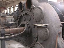
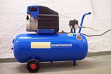
A compressor ( compressor ) is a machine ( fluid energy machine ) that an enclosed gas mechanical work feeding; Compressors for compressing of gases used. They increase the pressure and density of the gas. Machines in which a low compression is a side effect when transporting gases are called ventilators or blowers and are generally not counted among the compressors. Machines that increase the pressure of liquids are called pumps . Compressors that generate a negative pressure (vacuum) and work against the air pressure are called vacuum pumps .
Basics
If the volume of a gas is reduced by compressing it, one speaks of compression or compression. Corresponding devices are called compressors or compressors. During compression processes, an existing intake volume V 1 is compressed to a smaller volume V 2 with the operating pressure p 1 . There is an increased pressure p 2 in the smaller volume V 2 , and the gas is heated during the compression process.
Since the volume decreases during compression, it is crucial to indicate the respective pressure state for the volume flow. The usual specifications are the suction volume flow (based on suction pressure p 1 ), outlet volume flow (based on the final pressure p 2 ) and the standard volume flow (based on the standard state p = 101.3 kPa, T = 293.15 K = 20 ° C).
For compaction operations, shall remaining constant temperature the Boyle's law .
When applying this law, it must be ensured that p 1 and p 2 are absolute pressures. However, all pressure specifications for pneumatic systems refer to the overpressure Pe compared to atmospheric pressure. Otherwise pressure information will be specially marked.
- Pressure specifications in pneumatics relate to overpressure
- Pressure gauges in pneumatics are set to overpressure
Delivery quantity and operating pressure
The achievable pressure and the delivery quantity are used to identify a compressor. The delivery quantity is the volume of gas released per period; For small systems it is given in liters / min, otherwise in m 3 / min. Often common but misleading is the specification of the (theoretical) suction power as the product of speed and displacement . It says nothing about the actual delivery rate, since the volumetric degree of filling is neglected.
Parameters
- Delivery quantity - volume of the dispensed fluid per unit of time.
- Operating pressure - achievable overpressure.
- Pressure ratio = final pressure / suction pressure
- Delivery rate - Describes the ratio of the conveyed to the theoretically possible (due to the geometry) volume flow.
In order to be able to compare compressors of different types and operating points better, the standard volume flow is often considered. This is the volume flow of the compressor converted to standard conditions (temperature, pressure, humidity).
Designs
Reciprocating compressors
A distinction is made between reciprocating compressors and rotary lobe compressors.
In reciprocating compressors, the gas in a cylinder is sucked into the working chamber by a piston moving back and forth, where it is compressed and then expelled again. These compressors work cyclically, have low volume flows and high pressure ratios . The suction and discharge valves are automatically operating plate valves.
There are different types of rotary piston or rotary compressors ( Roots blowers , vane compressors , screw compressors, scroll compressors ). What they have in common is that the working space is formed between the housing and one or more displacers (rotary pistons) that rotate or move on a circular path. The gas is sucked in and expelled through slits that the piston opens and closes as it moves.
Screw compressors
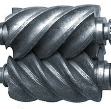
The screw compressor belongs to the group of rotating, twin-shaft positive displacement compressors with internal compression. It has a simple structure, small dimensions, a small mass, uniform, pulsation-free delivery and smooth running because it lacks oscillating masses and control elements. It reaches up to 30 bar overpressure.
history
The idea to build a screw compressor came up in 1878, but the geometry of the surfaces could not be created due to technical difficulties. About half a century later, in 1930, the technical prerequisites for manufacturing the complicated screw geometry were in place. In 1955, a Swedish engineer named Alfred Lysholm managed to manufacture and successfully use the world's first screw compressor. Initially, however, the compressor could not prevail over the conventional piston compressor. The internal losses at the screws were too great to speak of an effective compressor and, above all, of an alternative to the piston compressor. Another 40 years had to pass before the decisive point in improving the efficiency was finally found. Oil injection into the compressor stage reduces the loss rate considerably and at the same time serves as cooling for the compressor block. In addition, roller bearings could then be used instead of the plain bearings that had been common up until then . All in all, this knowledge led to very simply built, yet robust compressors. Screw compressors have now proven their worth - about half of all compressors currently in use are screw compressors.
functionality
Two rotors arranged in parallel, mechanically (usually by a pair of gears) forcibly coupled rotors with interlocking, helical teeth in a housing are the heart of this system. At the rolling line between the two shafts (the point where the two helical shafts touch) the passage for the medium to be conveyed is mechanically closed (by the toothing). The medium is located in the tooth channels and is held in it by the housing wall. It is conveyed in the axial direction. There are openings for the inlet (suction side) and outlet (pressure side) in the housing on the two end faces of the axles. The length of the rotors, the pitch of the teeth and the inlet and outlet openings must be adjusted so that there is no direct passage from the pressure to the suction side, i.e. no backflow can occur. Apart from the losses, the volume flow of the medium is proportional to the speed .
The medium (for example air) flows into the tooth gears on the suction side until the gear closes at the rolling point when turning further on the suction side. It now forms a helical air hose around the rotor . With further rotation, the toothing opens on the pressure side, and the air is pumped out of the machine by further rotation.
In order to achieve largely impulse-free compression with a high degree of efficiency, the air must already be compressed in the compressor so that the pressure at the end of the compression is as equal as possible to the pressure on the pressure side. In addition, the gas is not immediately released to the pressure side. A wall is opposed to the opening of the tooth passage. As the shaft continues to rotate, the volume of the air hose is reduced because it is practically pressed against the wall, it is compressed. Now, depending on the pressure required, this compressed air hose can be released sooner or later. The degree of compression is therefore determined by the size and arrangement of the outlet opening.
Another possibility for internal compression of the air is to change the pitch of the toothing, which in this case decreases towards the pressure side. When the air hose migrates to the pressure side, its volume is reduced with a decreasing slope.
Turbo compressor

With turbo compressors , energy is added to the flowing fluid by a rotating rotor according to the laws of fluid mechanics. This design works continuously and is characterized by a low pressure increase per stage and high volume throughput. Radial and axial compressors are the two main types of turbo compressor. With axial compressors, the gas to be compressed flows through the compressor in a direction parallel to the axis. With a radial compressor, the gas flows axially into the impeller of the compressor stage and is then deflected outwards (radially). With multistage centrifugal compressors, a flow deflection is therefore necessary after each stage.
These compressors are used, for example, in exhaust gas turbochargers (mostly as radial compressors) or in turbine jet engines (mostly as axial compressors). Here, however, the pressure does not increase due to the narrowing channel cross section, but rather due to the fact that the space between the blades of such a compressor takes the form of a diffuser . Here the pressure and temperature increase while the speed decreases. In the rotating part of a compressor stage (impeller, rotor), the kinetic energy required for further pressure build-up is returned to the air.
Transonic compressor
A transonic compressor is understood to be a turbo compressor of axial or radial design, in which the flow velocity in the relative system (the observer “sits on the rotating rotor blade”) at least locally exceeds the speed of sound. The front stages of modern compressors in aircraft engines and gas turbines are usually designed to be transonic, as the temperatures here are still low and a higher Mach number is obtained with the same flow speed . The Mach number is the ratio of the flow velocity to the speed of sound; the latter is a function of the temperature and the chemical composition of the gas.
The advantage of transonic compressors is the high power densities, which is particularly important for aircraft engine compressors, since the system is very compact. These compressors are characterized by complex systems of compression surges, which make the design and stable operation of the compressor much more difficult. Another disadvantage are the high losses associated with the compression shocks, which can only be countered by complex three-dimensional blading and sophisticated profiles. The first stages of the low-pressure compressor in engines are usually designed to be transonic because of the large diameter of the rotors and the equality of speed of all units on the shaft.
Other types of compressors
- Liquid ring pump
- Reciprocating compressors
- ionic compressor
- Lamellar compressor
- Rotary compressor
- Swash plate compressor ( English wobble plate )
- Labyrinth piston compressor
- Screw compressors
- Roots blower
- Swash plate compressor ( Swash-Plate )
- Scroll compressor (" VW G-Lader ")
- Junkers free piston compressor , see also free piston machine
- Diaphragm compressor
- Side channel blower
Classification
Volume flow and final pressure
Turbo compressors deliver large volume flows at low compression end pressures, displacement compressors deliver high compression end pressures at low throughputs.
Oil free
Compressor types can also be divided into oil-lubricated and oil-free compressors.
Open or hermetic
In refrigeration technology, there is an additional distinction:
- Fully hermetic compressors - the motor and compressor are located in an encapsulated, welded housing and are in direct contact with the refrigerant ; the housing cannot be opened for repairs
- Semi-hermetic compressors - motor and compressor are in the same housing, the housing can be completely dismantled and repaired using the screwed cover
- Open compressor - the compressor is driven by belts, gears or gears, the housing can be completely dismantled and repaired using the screwed cover
Drive types
The drive by electric motors enables a variable speed in a wide range and thus the controllability of the delivery quantity. Maintenance costs are low, but operating costs depend on the electricity price.
When driven by an internal combustion engine , controllability is severely limited, since internal combustion engines can only be operated efficiently and for a long time in a certain speed range. In the meantime, compressors driven by gas engines are also available as combined heat and power systems. The low gas price in relation to the electricity price means that the operating costs are low. If a commercial enterprise with a continuous need for compressed air can use the waste heat generated by the combustion engine and compressor to heat the building, the higher investment costs pay off due to the savings in heating costs.
Applications
- Respiratory protection compressor
- Compressed air system
- Air conditioning compressor
- Air pump
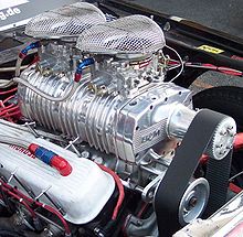
- Engine charging , as an aid to "forced filling" of the engine with additional air or gas mixtures to increase performance
See also
Web links
Individual evidence
- ↑ " Efficient systems ( Memento of the original from August 4, 2016 in the Internet Archive ) Info: The archive link was automatically inserted and not yet checked. Please check the original and archive link according to the instructions and then remove this notice. " Marani Aug 4, 2016.
- ↑ Significant people in the history of the Atlas Copco Group ( Memento of the original from April 2, 2016 in the Internet Archive ) Info: The archive link has been inserted automatically and has not yet been checked. Please check the original and archive link according to the instructions and then remove this notice. Atlas Copco Group website. Retrieved May 29, 2012.
- ↑ Reports on compressor systems with waste heat utilization in energy and management , in the Industrieanzeiger and on the Hannover Messe website . accessed in September 2016.


