
Welding arc
The free-burning welding arc is created by an electrical gas discharge, mostly under conditions of normal air pressure . From a physical point of view, it is a plasma - a particle mixture of metal vapor from the electrodes, neutral gas atoms, ions and electrons. The column of the arc has a temperature between 4,000 and 16,000 Kelvin . The arc is therefore suitable as a technical tool for producing welded joints using a large number of different welding processes .
The welding arc burns with currents ranging from a few amperes to a few kiloamperes at a voltage of 8 to 60 volts between a negatively polarized cathode and an anode .
Physical basics
Plasma condition
A gas mixture in the plasma state is in a special (fourth) physical state of matter at high temperatures. As the temperature rises, all matter passes through the three known states of aggregation (solid, liquid and gaseous) in order to pass into the conductive plasma state when the temperature rises further. The neutral atoms break down into electrons and positive ions.
The welding arc as an energy source

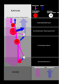
Temperature field of a TIG welding arc according to Wendelstorf

Potential distribution of TIG arcs in a protective gas atmosphere of argon and helium according to cited in

Arc build-up and voltage drop across the arc (schematic)
Charge carrier transport of an arc discharge according to cited in

Thermal conductivity of the plasma in different gases


The welding arc converts electrical energy into thermal energy . The electrical energy results from the product of the arc current , arc voltage and welding time , with the arc voltage being composed of the voltage drop at the anode , the cathode and the arc column:


- .

The major part of the energy turnover results from the anode and cathode drop areas. Less than 1/3 of the total energy is generated in the arc column. The extent of the cathode and anode drop areas is negligibly small compared to the length of the arc column.
Arcing processes
In order for an arc to burn, electrons have to escape from the cathode by thermal emission (at high cathode temperature ), field emission (at low cathode temperature) or thermal field emission as a mixed form of electron emission into the cathode drop area. There they are accelerated by the electric field and cause thermal ionization of the initially neutral gas. This releases more electrons and creates positive ions that migrate towards the cathode. The larger amount of electrons causes further ionization of neutral gas atoms by collision in front of and in the arc column, the amount of electrons continues to increase, ionized gas atoms migrate to the cathode, the electrons to the anode. At the same time, some of the ions combine with electrons to form neutral atoms ( recombination ). This process also continues in the anode fall area. Since the electrons have a much higher mobility than the positive ions, the charge transport is almost exclusively taken over by the electrons. The current flowing through the plasma causes a magnetic field that constricts the arc ( pinch effect ), which accelerates the plasma flow and improves the coupling of heat into the workpiece.
Arc characteristic

Measurable voltage drop during MIG / MAG welding
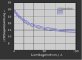
Theoretical arc characteristics of TIG arcs with different arc lengths according to Goldmann cited in

Arc characteristics for MAG welding according to the model EN 60974-1 and


With a constant arc length, the voltage drop across the arc changes as the arc current increases. This functional relationship between voltage and current is called the arc characteristic (see also current-voltage characteristic ). The welding voltage depends on the arc length and the composition of the plasma on the electrode geometry and the material composition of the electrodes.
Non-consumable electrode
For the arc during TIG welding in argon, the following functional relationship is given, which has been experimentally confirmed in the range of higher currents:

with as arc length.

Consumable electrode
The constant transfer of material makes it difficult to determine a static arc characteristic, but it can be done by measuring current and voltage and simultaneous slow-motion recordings. When measuring voltage in a technical environment (e.g. MIG or MAG welding), it must be taken into account that in addition to the voltage drop across the arc, the voltage drop across the so-called free wire length , across the contact tube and e.g. T. is also measured over the workpiece :


- .

The functional relationship between the welding voltage and the welding current can be described as a model for welding under CO 2 using the following function:
- .

Standard EN 60974-1: 2012 specifies standardized arc characteristics for the various arc welding processes, and the following model for gas-shielded metal arc welding with constant voltage:
- .

(The model is used to determine the working range of a power source.)
Arc types

Types of welding arcs according to

Arc types according to Linde


For welding, a distinction is made between different types of arcs, depending on the welding process and the technical-physical conditions involved, the main difference being whether the electrodes melt or not. Characteristics are also the type of current ( direct or alternating current ) or the type and composition of the protective gas in which the arc burns.
Melting electrodes melt under the thermal effect of the arc, whereby the liquid electrode material combines with the melted base material and forms the welded joint. Non-melting electrodes are only used to create an arc for use as a welding heat source. Direct current arcs burn with constant polarity. In the case of alternating current arcs, the polarity of the electrodes is continuously changed with the mains frequency or with another frequency generated.
Types of arc when welding with a non-consumable electrode
The TIG arc
Ignition of the arc
An arc between the non-melting tungsten electrode and the workpiece can be ignited without contact by a spark discharge . The high voltage of a high voltage source between the electrodes creates an ionizing spark channel within the surrounding neutral gas through which the arc can build up. After the ionized channel has been established, the welding power source must supply the energy required for the arc with sufficient speed to ignite an arc. That depends on the open circuit voltage of the voltage source and its circuit inductance. Under argon, a voltage of 1.2 to 3 kV is required to ignite an arc with an electrode gap of 1 to 3 mm.
The TIG arc can also be ignited by touching the electrodes and thus by thermal emission. However, this has technical disadvantages, such as damage to and contamination of the tungsten electrode. A variant of this type of ignition is the lift-arc ignition, in which the ignition takes place with a low current, which is increased to the required strength after the ignition of the arc.
Burning the direct current arc
The ignited arc burns in a steady state with constant arc length and under the same ambient conditions with constant current-voltage values. In real operation, however, it can show irregularities that are triggered by sudden displacements of the arc axis as a result of the migration of the cathode spot. The cathode spot moves to the areas of greater concentration of embedded oxides (thorium, lanthanum, zirconium, cerium). These are sintered into the tungsten electrode material in order to reduce the work function of the electrons and thereby enable higher electron emission and better ignition properties. The effect of the migration of the cathode focal point occurs particularly with a high current load.
Burning the AC arc

Time curve of the open circuit voltage, arc voltage and current in TIG AC welding

Dynamic arc characteristic for TIG aluminum welding according to


The TIG alternating current arc changes its polarity when the polarity of the welding power source changes. It goes out when the current falls below a minimum, whereby the conductive current channel cools down and the ionization drops quickly. The time constant with which the conductance of the gas column decreases is called the thermal time constant (τ). The conductance ( ) of the continuously burning arc column depends on the stored thermal energy ( ) of the arc column and the arc power ( ). In the steady state, the electrical power supplied ( ) compensates for the heat losses ( ). If the supplied energy breaks down, the conductance decays with the thermal time constant τ, for which Mayr (cited in) describes a model:


- .

The re-ignition must take place within the time window given by τ. Dynamic properties of the welding power source are decisive for this, i. H. the ability to deliver high energy in a short time after the current has passed zero. The heated tungsten electrode supports reignition by emitting thermal electrons if it is polarized as a cathode. If the workpiece side (e.g. made of aluminum) is polarized as the cathode, the electron emission is very low. Re-ignition is difficult. A voltage spike occurs during arc ignition. The arc voltage after re-ignition is higher than with reversed polarity, since the thermal emission of the weld pool is lower, which leads to a resulting DC component of the voltage. An asymmetrical dynamic UI characteristic is created.
Types of arcs when welding with a consumable electrode
The MIG / MAG arc

Ignition of an arc during MIG / MAG welding (schematic)

Material transfer in a short arc
Arc and material transfer with pulsed arc

Arc and material transfer in a spray arc


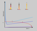
The wire is melted by the arc in different ways depending on the process variant and the welding parameters set. The shape of the material transition in MIG / MAG welding changes with increasing welding current and voltage. These merge continuously, the boundaries are blurred. As the arc voltage rises, the drop volume increases and the material transition becomes short-circuit-free. If the arc length is too great, the arc will break after the material transition. The number of drops increases with increasing current strength. At the same time, their volume decreases.
Igniting the arc
The arc for welding with a consumable electrode is ignited by briefly touching the electrode with the workpiece. The relatively high short-circuit current melts and evaporates the short-circuit bridge. The metal vapor has a high local pressure and high density, which means that the thermal ionization can be triggered by the applied voltage. An arc can ignite. Depending on the size of the contact area and the level of the short-circuit current, the arc can occur immediately or only after the process has been repeated several times. High no-load voltage, high short-circuit current, rapid current rise and a small contact area facilitate immediate arc ignition.
Burning of the short arc
The arc length changes cyclically. This is associated with shifts in the operating point of the welding current and welding voltage. In the phase of droplet detachment, as the droplet approaches the melt, the arc voltage is reduced until the droplet passes into the melt pool. A short circuit occurs, the current increases according to the inductivity of the welding circuit up to the maximum short circuit current. The rate of increase in current of the power source largely determines the type of droplet detachment. After the arc is re-ignited, the voltage increases sharply. The welding current falls again and adjusts itself according to the position of the arc operating point on the power source characteristic. The course of the momentary welding current is essentially determined by the dynamic properties of the welding power source. In modern welding power sources , these properties are specifically generated through control and regulation . During the drop short circuit, the measurable voltage does not collapse completely, as the heated free wire length has a clear, dynamically changing resistance.
Burning of the pulsed arc
When welding with a pulsed arc, a basic voltage is regularly superimposed on an increased pulse voltage, whereby a basic current and a pulsed current alternate with a given frequency and pulse time. During the basic current phase, the arc burns with low power, the filler metal is melted, the weld pool is kept liquid. During the impulse phase, a large drop forms, which is detached by the growing magnetic constriction ( pinch effect ). Depending on the wire diameter and the electrode material, the setting values must be selected in such a way that a drop is detached with each current pulse.
Pulse welding has become widely accepted today because of various advantages for welding thinner sheets. The heat input can be reduced and controlled, thin sheets can be welded with thicker wires, the deposition rate is higher, and spatter can be greatly reduced. When welding thin sheet metal, it is particularly important to introduce as little heat as possible into the component because of the heat distortion. For this reason, various manufacturers of welding power sources have developed processes to reduce the welding power while maintaining the same deposition rate and to keep spatter formation low by using special pulse shapes and controlling the wire feed.
Burning the spray arc
The spray arc burns continuously without short circuit interruption. The material transfer from the wire electrode into the weld pool is fine droplets. Relatively high thermal energy is introduced into the weld metal, which is why the heat affected zone and thus also the workpiece distortion are greater than with a short arc. This type of arc is used to weld thicker sheets.
Interaction between voltage source and arc
Operating point for short arc welding as the intersection of the arc characteristic and the static UI characteristic of the voltage source
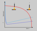
Operating points in TIG welding with a "falling" UI characteristic of the voltage source
Scheme of the internal regulation for inert gas welding


In order to generate an arc, a voltage source (technically: welding current source) of suitable power and UI characteristic is required . A current-voltage operating point is established depending on the arc and voltage source characteristics.
Non-consumable electrode
When welding with electrodes that do not melt away ( TIG welding ), the aim is to keep the welding current as constant as possible, even when the length of the arc changes due to changes in the distance between the electrode tip or due to magnetic influences. This is achieved by so-called "falling" UI characteristics of the voltage source.
Consumable electrode (MIG / MAG welding)
When welding with a consumable electrode, the working point constantly changes its position. The reasons for this are the change in length of the arc and short circuit during the droplet transfer into the weld pool in the case of a short arc or the systematically generated change in current in pulse welding. The deflection of the arc by magnetic fields and movement of the arc attachment points on the anode and cathode also lead to shifts in the operating point. In order for the welding process to be maintained, an equilibrium between the amount of melted wire and the wire feed speed must be established on average over time. The dynamic shifting of the operating point must not hinder the continuous seam formation. Every time the arc is disturbed, the state of equilibrium must be re-established, then one speaks of a stable arc.
In gas-shielded metal arc welding, power sources with an approximately constant voltage are used over larger current ranges. This allows the process to stabilize itself through “internal regulation”. If the melting speed is lower than the feed speed of the wire feed, the end of the wire approaches the surface of the weld pool, the arc becomes shorter and the current strength increases. The melting speed increases as a result and exceeds the conveying speed. The arc becomes longer and the amperage drops again. This process regulates the arc length and ensures the balance between melting and wire feed speed. The effect described has the result that the welding current intensity is set by selecting the wire feed speed.
For welding with thicker wires (> 2.5 to 3 mm) as in submerged arc welding , power sources with a falling UI characteristic are used because the "internal" control for stabilizing the arc is not fast enough. The wire feed speed is changed via an "external" control to ensure the melt-off equilibrium. A higher arc voltage results in a higher speed of the feed motor, which means that more wire is fed in with a long arc, until the desired arc length is reached again.
Even in manual metal arc welding power sources are used with falling UI characteristic line to ensure approximate current Konstanz.
Dynamic arc behavior

Dynamic characteristics of a short arc

Dynamic characteristics of a pulsed arc


The dynamic properties and control of the respective power source and the burning conditions of the arc can be read off in dynamic arc characteristics. When welding with the short arc (material transfer with short-circuit formation), short-circuit phases alternate with burning phases. The arc length changes cyclically. This is associated with shifts in the operating point of the welding current and welding voltage. In the phase of droplet detachment, the arc voltage drops until the droplet forms a short circuit and the current rises to the maximum short circuit current. The short-circuit bridge breaks when the metal drop becomes detached. When the bridge between the electrode and the workpiece is torn open, the voltage rises very quickly, as there is an increased voltage requirement to ignite the arc. The incipient drop in current is very slow because of the inductances in the welding circuit. The re-ignition takes place at a relatively high electrical power. Part of the liquid bridge can evaporate explosively, and splashes occur if the rate of increase in current has not been reduced by a sufficient choke effect in the circuit. However, if the rate of increase in current is too low, droplet detachment can be hindered and the process can become unstable.
When welding with a pulsed arc, an increased pulse voltage is regularly superimposed on a basic voltage. Base current and pulse current alternate continuously.
The smaller the spread of the dynamic characteristics, the more stable the arc process.
External influences on the arc
The voltage of the arc column depends on the composition of the plasma and the temperature distribution, as well as on the distribution of the flow in the column. The gas properties (such as ionization energy , thermal conductivity , density , degree of ionization , conductivity of the arc column) affect the temperature distribution in the arc (see Eggert-Saha equation ).
Gases
Physical gas properties have an effect on the technical welding properties via the arc properties such as the material transition, the wetting behavior, the penetration depth and shape, the welding speed and the ignition behavior. Gases with low ionization energy (e.g. argon) make it easier to ignite and stabilize the arc compared to gases with high ionization energy (e.g. helium). The targeted doping of inert gases with chemically active components such as CO 2 or O 2 in the vpm range results in arc stabilization that can improve the welding result. The dissociation energy of polyatomic components in the gas increases the heat input into the base material during welding due to the energy released during recombination.
The thermal conductivity of the shielding gas influences the weld pool temperature and thus the escape of gases from the weld pool and the shape of the seam. The achievable welding speed is also determined by the gas properties.
Magnetic field

Magnetic field of a moving charge in an arc

Magnetic field around a current-carrying conductor


The arc consists of moving charge carriers that create an electric field. According to the laws of electrodynamics (see also), an electrical field that changes in terms of location and time generates a magnetic field that changes in location and time. For a single moving charge carrier with a speed , there is a vector of the magnetic field strength at the distance :


![\ overrightarrow {H} = {\ frac {ev_ {e}} {4 \ pi r ^ {{2}}}} [{\ textstyle \ overrightarrow {r}} _ {{0, e}} \ times {\ textstyle \ overrightarrow {v}} _ {{0, e}}]](https://wikimedia.org/api/rest_v1/media/math/render/svg/dacae91a4ffbb12429cdd6103442734b78f77efe)
with as the vector product of the respective unit vectors.
![[{\ textstyle \ overrightarrow {r}} _ {{0, e}} \ times {\ textstyle \ overrightarrow {v}} _ {{0, e}}]](https://wikimedia.org/api/rest_v1/media/math/render/svg/ea744c6a9cdc6a344e2d5f7a8560256d8cf65071)
The sum of all moving charge carriers in the arc creates a magnetic field concentric around the arc. As long as the charge carrier density is evenly distributed radially around the arc axis and the surrounding material is homogeneously distributed, the arc can burn in a straight line between the anode and cathode. Disturbances in the material distribution in the vicinity of the arc, inhomogeneities in the gas composition, one-sided cooling of the arc from the outside or changes in the current path lead to undesired deflections of the arc, to the so-called blowing effect with disturbances to the welding process.
Diagnostic information from the welding arc
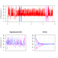
Welding current of a MAG arc with density distributions of signal segments

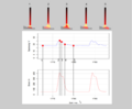
Spectra of two TIG arcs with 130 A and 90 A in argon as a protective gas

Spectra of two argon arcs of different lengths and with different welding currents. A longer arc length, even with increasing current strength, leads to a lower intensity of individual spectral lines, since the charge carrier density decreases. (to)

Radiation densities over the wavelength for selected temperatures according to Planck's law of radiation
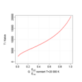
Temperature function for the wavelengths 440/740 nm according to


Electrical quantities
The energy conversion of the arc is significantly influenced by the electrical parameters of the arc current and voltage. With MIG / MAG welding , the signals have characteristic curves depending on the type of arc. If these signals are measured digitally, frequency distributions can be formed over predetermined time windows, the parameters of which are adequately mapped by the signals. The histogram, as an estimate of the frequency density , has long since developed into a descriptive instrument for dynamic arc behavior during welding.
Light emission
The atoms and molecules in the arc exist in the status of characteristic discrete energy contents. The energy status changes after the absorption or release of energy in specific energy quantities. Energy emission occurs as an electromagnetic wave when the energy status changes from a higher level to a lower one:

With
- Planck's quantum of action Planck's quantum of action
- frequency
- Speed of Light
- Wavelength.


Arcs emit light when excited atoms fall back to a lower energy level. Since excited atoms of different elements are present in the welding arc, line spectra of the elements involved result depending on the arc temperature and particle density. Essential parameters of the arc, such as the arc length, the arc temperature and the arc stability, can be determined from a spectrum. In addition to the line spectrum, the interaction between electrons and ions creates continuous radiation, the proportion of which increases as the plasma temperature rises.
Assuming the plasma of an arc in local electrodynamic equilibrium, the arc temperature can be calculated from the electron temperature. The latter can be determined with the help of measured relative intensities of individual spectral lines.
In addition to the radiation from the arc column, electromagnetic radiation from the area of the arc has other sources, such as the attachment points on the electrodes, the heated drop material, the hot additional material and the weld pool, which emit a continuous light spectrum, the intensity of the light being essentially of the arc column (including the arc length) is determined.
An integral consideration of the emitted light over a larger spectral range can also provide important information. Argon radiation has a central wavelength of 750 nm (from 550 to 850 nm) and metal vapor radiation (mainly iron) has two clusters around 420 nm and 520 nm. If spectrally selective photodiodes are used, the components from the individual radiation sources and components of the arc can be filtered . In this way, the pulse welding process can be controlled spectrally. With the help of two spectrally sensitive photodiodes, the plasma light is spectrally broken down. The intensity of the light from the metal ions is recorded by a blue / ultraviolet photodiode and that of the protective gas argon is recorded by a red / infrared photodiode. The difference between the intensities of the two channels is calculated and a switch-off signal for the pulse when a preset plasma temperature is reached is obtained from this. The Planchsche radiation law :

provides the relationship between the emitted energy as a function of the wavelength of the light and the temperature. At given temperatures, specific radiation densities result over the wavelength. From this, the plasma temperature can be estimated if information is available about two emission values of different wavelengths, as provided by two photodiodes of different spectral sensitivity (diodes with a sensitivity maximum at 440 nm and 740 nm are used). Assuming both wavelengths, the quotient of the two intensities is specific for the plasma temperature:
- .


If the quotient of the radiation densities is calculated over all temperatures, the result is a monotonically increasing function:
- .

Sound emission

Excerpt from the current and voltage signal of a MAG short arc welding, the sound signal and the calculated signal from the current and voltage signal

Comparison of the measured and calculated sound signal


In addition to the optical image of the weld pool and the filler material, the sound emission of the arc provides the arc welder with essential information about the process quality, i.e. H. the type of droplet transfer, its stability and thus the expected quality of the welded joint. The sound pressure and sound frequency depend on the electrical energy of the arc and the type of material transition. The relationship can be described as follows:
- With
- Sound signal
- Voltage signal
- Current signal


The factor k depends, among other things, on the speed of sound and the adiabatic expansion coefficient of air. The relationship described was derived from measurements on electric arc furnaces. The qualitative description can be transferred to welding arcs. The sound is generated by the vibrating arc column, not the anode and cathode drop areas. The MIG / MAG welding process is characterized by alternating arc cycles of arc ignition and burning and subsequent droplet transfer. These cycles can be clearly recognized both in the electrical signals and in the sound signal. The arc ignition causes a high acoustic peak value and the drop short circuit causes a lower value in both signals, whereby the acoustic event occurs delayed after the electrical one, but is qualitatively the same.
credentials
- ↑ a b c d e f g h i j k l M. Schellhase: The welding arc as a technological tool. Verlag Technik, Berlin 1985, ISBN 3-87155-100-7 .
- ↑ a b G. Fußmann: Introduction to Plasma Physics. ( Memento of the original from February 18, 2016 in the Internet Archive ) Info: The archive link was inserted automatically and has not yet been checked. Please check the original and archive link according to the instructions and then remove this notice. Lecture notes. HU Berlin, 2001.
- ^ J. Wendelstorf: Ab initio modeling of thermal plasma gas discharges (electric arcs). Dissertation . TU Braunschweig, 2000.
- ↑ Ю.К. Топчий, В.П Каменев: Установка для определения распределения потенциала в дуге с неплавящимся оэдения Сварочное производство, Москва 1974, №1, c. 51-52. (Ju. K. Topci, VP Kamenev: Device for determining the potential distribution in the arc on a non-consumable electrode. Savr. Proizvod., Moscow 1974, 1, pp. 51-52).
- ↑ G. Hertz, R. Rompe: Introduction to plasma physics and its technical application. Akademieverlag, Berlin 1968, DNB 451073819 .
- ↑ A. Hübner: Investigations into the influence and effects of nitrogen additives in protective gas on the hot crack behavior of selected nickel base materials that are sensitive to hot cracks. Dissertation. University of Magdeburg, 2005, DNB 979123410 .
- ^ A b K. Goldman: Electric Arcs in Argon: Volt-Amp and Volt-Arc Gap Characteristics. In: Physics of the Welding Arc. London 1966, pp. 17-22.
- ↑ a b В.Р. Верченко: Статические характеристики дуги при сварке плавящимся электродом в среде защитных газоваитных. Автоматическая сварка, 8 - (1958), C. 5-7 (VR Vercenko: Static characteristics of the arc when welding with a consumable electrode under protective gas. Avt. Svarka, 1958, pp. 5-7).
- ↑ YuMing Zhang: Real-time weld process monitoring. Woodhead Publishing, 2008, ISBN 978-1-84569-268-1 .
- ↑ EN 60974-1: 2012 Arc welding equipment - Part 1: Welding power sources .
- ↑ PanGas: Welding connects - welding, cutting and shielding gases. Information sheet 099,7305.2012-11.V2.3000.UD ( Memento of the original from October 6, 2014 in the Internet Archive ) Info: The archive link was inserted automatically and has not yet been checked. Please check the original and archive link according to the instructions and then remove this notice. .
- ↑ O. Mayr: Contributions to the theory of the static and dynamic arc. In: Archives for electrical engineering. 37 (1943), H. 12, pp. 588-608.
- ↑ S. Berger: Model for the calculation of the dynamic electrical behavior of rapidly extended arcs. Dissertation. ETH Zurich, 2010.
- ↑ DIN 1910-100: 2008-02: Welding and related processes - Terms - Part 100: Metal welding processes with additions to DIN EN 14610: 2005.
- ↑ M. Schellhase, 1965, p. 36.
- ↑ The Linde shielding gases for welding. Sales document A402 from Linde Gas GmbH, 2006.
- ↑ M. Bäker: The Maxwell equations (almost) without formulas. Blog Dragons live here .
- ^ W. Westphal: Physics. Springer, 1963, p. 249.
- ↑ Daniel Flávio Vidal Bebiano: Monitoração e localização de defeitos na tig Soldagem utilizando técnicas de espectrometria. Dissertation. Universidade de Brasília, 2008, (TIG welding monitoring and troubleshooting using spectrometric techniques).
- ↑ Pengjiu Li Yuming Zhang: Robust Sensing of Arc Length. In: IEEE Transactions on instrumentation and measurement. 3, 2001, pp. 697-740.
- ↑ a b c d e G. Heinz, H. Schöpp, L. Dorn: Optimization of the energy input of pulsed arc joining processes by means of spectrally sensitive sensors. ( Memento of the original from November 3, 2014 in the Internet Archive ) Info: The archive link was automatically inserted and not yet checked. Please check the original and archive link according to the instructions and then remove this notice. Final report IGF 14.607, GFaI e. V., INP Greifswald, Technical University Berlin, 2008.
- ↑ F. Erdmann-Jesnitzer, D. Rehfeldt: Method and device for monitoring the welding process in electric welding processes, in particular arc and electro -slag welding processes. Patent of the Swiss Confederation 507769, 1971.
- ↑ Daniel Flávio Vidal Bebiano, Fernand Díaz Franco: REAL TIME WELDING DEFECTS USING MONITORIMENT SPECTROMETRY. In: ABCM Symposium Series in Mechatronics. Volume 3, pp. 784-792.
- ↑ MS Węglowski: Investigation on the arc light spectrum in GTA welding. In: Journal of Achievements in Materials and Manufacturing Engineering. Issue 1-2, 2007, pp. 519-522.
- ↑ a b c E. H. Cayo, SC Absi Alfaro: A Non-Intrusive GMA Welding Process Quality Monitoring System Using Acoustic Sensing. In: Sensors. Issue 9, 2009, pp. 7150-7166.
- ↑ EH Cayo, SC Absi Alfaro: Weld transference modes identification through sound pressure level in GMAW process. ( Memento of the original from July 13, 2014 in the Internet Archive ) Info: The archive link was automatically inserted and not yet checked. Please check the original and archive link according to the instructions and then remove this notice. In: Journal of Achievements in Materials and Manufacturing Engineering. Issue 1, 2008, pp. 57-62.
- ^ MG Drouet, D. Nadeau: Acoustic measurement of the arc voltage applicable to arc welding and arc furnaces. In: J. Phys. E: Sci. Instrum. Volume 3, 1982, p. 268.