Fuel tank

The fuel tank is a container in which fuel - for example gas, petrol or diesel - is stored for operating an internal combustion engine . In contrast to a storage container , the tank is connected to a machine or a burner .
On a ship, fuel tanks are called " bunkers " - a term that dates back to the days of steamships using hard coal as an energy source.
automobile

Until the 1970s, tanks were often located behind the rear axle in or under the trunk. There were also tanks in front of the dashboard in the engine compartment, so the vehicle didn't need a fuel pump. For safety reasons, the fuel tank in modern automobiles is usually located above the rear axle or in front of it under the rear seats. It can be made of aluminum , steel or plastic . Plastic fuel tanks do not corrode and can be better adapted to the shape of the vehicle floor for manufacturing reasons . Complex geometries can also be achieved with highly developed steels. A thermoplastic , HDPE ( high density polyethylene ) colored with carbon black , is used as the plastic . The black coloring makes the HDPE more resistant to sunlight, further inner layers serve as a barrier layer for the tank contents. With plastic tanks, it is important to have a noticeable conductivity for electrical current in order to avoid sparks that could otherwise arise from electrostatic discharge .
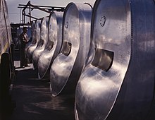
Truck tanks are often built from aluminum alloys to save weight.
For gas vehicles, steel or fiber composite tanks are used depending on the type of gas ( LPG or natural gas vehicle ). They must withstand the pressure of the compressed or liquefied fuel.
Manufacturing process for plastic fuel tanks (KKB)
Plastic fuel tanks are made in extrusion blow molding . In small series, e.g. B. in motorcycle tanks, the rotation melting process can also be used.
After removal from the tool, the KKB blank (“bubble”) is placed in a calibration system. Various methods are available for calibrating the KKBs. These are in detail:
- Water bath calibration: held in a calibration basket with individually adjustable elements; Build-up of a regulated internal calibration pressure with compressed air in the mbar range; defined dwell time under water
- Air calibration: recording in one (or several due to cycle time reasons) calibration nests; Build-up of a regulated calibration pressure or flushing pressure (dissipation of thermal energy); defined dwell time in the calibration nest
- Calibration mold: reshaping of the KKB in a contour-milled cavity ; Build-up of a regulated calibration or flushing pressure (dissipation of thermal energy); defined dwell time in the calibration form
Combinations of the individual calibrations can also be installed in series if this is necessary due to the production speed.
In these systems, the KKB is kept in shape at the important points - system and assembly areas. During the cooling phase of the hot KKB, there would otherwise be an uncontrolled deformation due to shrinkage and it could no longer be installed in the vehicle. Other possible errors due to insufficient calibration can be, for example, fluctuating volumes as a result of sink marks.
In further work steps, holes are cut to insert the fuel pump and the sender for the fuel gauge and weld nipples. Chips that have fallen into the KKB must be removed before further assembly. In addition, other components such as holders, angles, clips and the filler pipe can be attached. After the attachment parts have been fully assembled, a leak test is carried out.
How the fuel tank works
Refueling
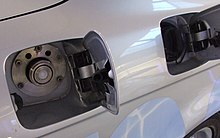
The fuel, petrol or diesel , flows into the container through the filler neck and the filler pipe . The air contained therein escapes to the outside via the nipple of the tank ventilation (→ fuel evaporation ). Especially with more volatile petrol, the petrol vapor in modern petrol stations is returned from the decreasing gas space in the vehicle tank via a separate, thinner line in the pump and hose to the underground storage tank, where the gas space increases accordingly. This gas displacement system is also used when refilling the underground tanks and the delivery vehicles and is done for reasons of air pollution control, the reduction of the risk of fire and the significant reduction in transfer losses. The refueling venting nipple on the tank must be positioned in such a way that the filling volume always remains the same when the vehicle is tilted 4 ° during refueling. In addition, the cross-section must be designed so that a filling speed of 50 liters per minute can be achieved. This is a test value of various automobile manufacturers, since the filling speed of public fuel pumps is much lower.
When the inflowing fuel or gas bubbles rising from it rise up in the filler pipe and reach the fuel nozzle, it switches off and the tank is filled. Therefore, after the fuel nozzle has been switched off for the first time, refueling can still be carried out, as the fuel surface has calmed down and no further gas bubbles arise due to the turbulence of the inflowing fuel. With fuel tank systems in commercial vehicles with a tank volume of 1000 liters and more, refueling after switching off is the rule. The diameter of the tank opening is about 10 centimeters and the nozzle cannot be positioned well. The turbulence is also more extreme. Refueling allows more consumption of up to 150 liters after switching off, i.e. a driving distance of over 400 kilometers.
Operation of the tank
In order to be able to absorb the expansion of the fuel when heated, either the fuel tank is designed to be around 15 to 20% larger than the specified filling volume or there is an additional so-called expansion volume. With a nominal volume = tank capacity of 60 liters, this means a fuel tank volume of around 70 liters.
The tank is vented during operation through the operational vent, also known as the fuel evaporation system , which has a smaller diameter than the refueling vent . The service venting nipple is generally attached to the highest point of the tank. The operating ventilation must not be open when refueling, as otherwise the tank could be filled up to its maximum volume. If the fuel were to expand when exposed to sunlight, it could flow up to the activated carbon filter and destroy it.
The operating ventilation leads to the activated carbon filter so that the hydrocarbons do not get into the environment. As already mentioned elsewhere , the activated carbon filter is emptied of the enriched hydrocarbons during operation via an electronically controlled valve, depending on the engine control and the load conditions of the engine. For this purpose, the connection to the fuel tank is closed with the valve so as not to generate a negative pressure there. The air to empty the activated carbon filter is drawn in through a separate fresh air opening on the filter housing. In order to prevent fuel from running at a vehicle rollover in the activated carbon filter and exiting into the environment through the fresh air opening of the filter is in the line, a roll-over-valve a, rollover valve installed.
The operating ventilation is closed during refueling either by a mechanical lever that is actuated through the tank cap, or by an electronically controlled valve in the line to the activated carbon filter.
Environmental requirements
Due to ever stricter legal regulations, especially in the United States and there in particular California , the emission of hydrocarbons has to be further reduced. The registration and thus the sale of vehicles in California depends on the emission of these hydrocarbons. This applies to the entire vehicle - not just to the fuel tank and the lines. These requirements are gradually becoming binding in Europe too, so that the choice of materials plays an increasingly important role in the development and manufacture of fuel tanks.
The HDPE plastic normally used for the tank is permeable to hydrocarbons at the molecular level. The enrichment of the HDPE with fuel is also a problem for recycling , as the walls of the tank "soak up" with the hydrocarbons. There are several ways to prevent this:
- One possible method is to fluorinate the inside of the tank during the inflation process. For this purpose, the completely inflated tank is flushed with fluorine and then cleaned of fluorine with nitrogen . The fluorine forms a protective layer on the inside of the tank and reduces the emission of hydrocarbons. This technique, while still in use, has been out of date for years. It no longer meets the requirements placed on modern fuel tanks.
- Another outdated technology is the use of Selar , a mechanical mixture of PE and PA , as the two plastics cannot be combined due to their molecular structure. A granulate mixture of these plastics is filled into the extruder and thus mixed mechanically. PA has the advantage that the hydrocarbons do not diffuse through and thus diffusion is reduced even with Selar . The PA molecular chains can be imagined as an embedded labyrinth in the PE.
- The use of multilayer tanks is common today. The wall of such a tank consists from the outside to the inside of black PE, adhesion promoter , [ethylene vinyl alcohol] copolymer (EVOH), adhesion promoter, regranulate made of PE and natural-colored = whitish PE. The bonding agent is required to create a chemical bond between PE and EVOH.
Plastic fuel tank test method
Plastic fuel tanks are exposed to a wide variety of stresses. In order to simulate these in new developments, there are different tests, two of which are described here as examples. There are a number of other tests that extend over several weeks specifically for checking the above-mentioned hydrocarbon enrichment and diffusion.
- Drop test: The KKB bladder is filled with glycerine (nominal volume) and cooled to −40 ° C. It is then dropped from a certain height. In this drop test, there must be no visible cracks or breaks on the visible side of the blank.
- Fire test according to ECE R34: The completely assembled fuel tank is installed in a vehicle - usually only the rear end - and then exposed to an open fire over a grate for two minutes. During this fire test, there must be no leaks on the tank or the filler pipe.
literature
- Hans-Hermann Braess, Ulrich Seiffert: Vieweg Handbook Motor Vehicle Technology, 2nd edition, Friedrich Vieweg & Sohn Verlagsgesellschaft mbH, Braunschweig / Wiesbaden 2001, ISBN 3-528-13114-4
- Jan drummans: The car and its technology , 1st edition, Motorbuchverlag, Stuttgart 1992, ISBN 3-613-01288-X
- Peter Gerigk, Detlev Bruhn, Dietmar Danner: Motor vehicle technology , 3rd edition, Westermann Schulbuchverlag GmbH, Braunschweig, 2000, ISBN 3-14-221500-X
- Max Bohner, Richard Fischer, Rolf Gscheidle: Expertise motor vehicle technology , 27th edition, Verlag Europa-Lehrmittel, Haan-Gruiten, 2001, ISBN 3-8085-2067-1

