
Multiview orthographic projection: Difference between revisions
m ISBNs (Build KE) |
→Section{{anchor|Cross section}}: cropped |
||
| (245 intermediate revisions by more than 100 users not shown) | |||
| Line 1: | Line 1: | ||
{{Short description|Technique of illustration}} |
|||
{{Redirect|Planform|wing planform of aircraft|planform (aeronautics)}} |
|||
{{Views}} |
{{Views}} |
||
[[File:Convention placement vues dessin technique.svg|thumb|right|200px|Symbols used to define whether a projection is either Third Angle (right) or First Angle (left).]] |
|||
With '''multiview orthographic projections''', up to six pictures of an object are produced, with each projection plane parallel to one of the coordinate axes of the object.<ref>{{Citation |author=Ingrid Carlbom, Joseph Paciorek |title=Planar Geometric Projections and Viewing Transformations |journal=[[ACM Computing Surveys]] |volume=10 |issue=4 |pages=465–502 |year=1978 |doi=10.1145/356744.356750}}</ref> |
|||
The views are positioned relative to each other according to either of two schemes: ''first-angle'' or ''third-angle'' projection. |
In [[technical drawing]] and [[computer graphics]], a '''multiview projection''' is a technique of illustration by which a standardized series of [[orthographic projection|orthographic]] [[two-dimensional]] pictures are constructed to represent the form of a [[three-dimensional]] object. Up to six pictures of an object are produced (called ''primary views''), with each projection plane parallel to one of the coordinate axes of the object. The views are positioned relative to each other according to either of two schemes: ''first-angle'' or ''third-angle'' projection. In each, the appearances of views may be thought of as being ''projected'' onto planes that form a six-sided box around the object. Although six different sides can be drawn, ''usually'' three views of a drawing give enough information to make a three-dimensional object. |
||
[[File:3D projection views.png|thumb|left|Projection views of a simple house from the book "Radford's mechanical drawing" (1912)]] |
|||
These three views are known as '''front view''' (also [[elevation view]]), '''top view''' or [[plan view]] and '''end view''' (also '''profile view''' or [[section view]]). |
|||
When the plane or axis of the object depicted is not parallel to the projection plane, and where multiple sides of an object are visible in the same image, it is called an ''auxiliary view''. |
|||
==Overview== |
==Overview== |
||
[[File:Graphical projection comparison.png|thumb|right|Comparison of several types of [[graphical projection]], including ''elevation'' and ''plan'' views]] |
|||
To render each such picture, a ''[[Line (geometry)#Ray|ray]] of sight'' (also called a ''projection line'', ''projection ray'' or ''line of sight'') towards the object is chosen, which determines on the object various points of interest (for instance, the points that are visible when looking at the object along the ray of sight); those points of interest are mapped by an [[orthographic projection]] to points on some [[Plane (geometry)|geometric plane]] (called a ''[[projection plane]]'' or ''[[image plane]]'') that is perpendicular to the ray of sight, thereby creating a 2D representation of the 3D object. |
|||
Customarily, two rays of sight are chosen for each of the [[Cartesian coordinate system|three axes]] of the object's coordinate system; that is, parallel to each axis, the object may be viewed in one of 2 opposite directions, making for a total of 6 orthographic projections (or "views") of the object:<ref>{{Citation |author=Ingrid Carlbom, Joseph Paciorek |title=Planar Geometric Projections and Viewing Transformations |journal=[[ACM Computing Surveys]] |volume=10 |issue=4 |pages=465–502 |year=1978 |doi=10.1145/356744.356750|citeseerx=10.1.1.532.4774 |s2cid=708008 }}</ref> |
|||
* Along a vertical axis (often the ''y''-axis): The ''top'' and ''bottom'' views, which are known as ''plans'' (because they show the arrangement of features on a horizontal plane, such as a floor in a building). |
|||
* Along a horizontal axis (often the ''z''-axis): The ''front'' and ''back'' views, which are known as ''elevations'' (because they show the heights of features of an object such as a building). |
|||
* Along an orthogonal axis (often the ''x''-axis): The ''left'' and ''right'' views, which are also known as ''elevations'', following the same reasoning. |
|||
These six planes of projection intersect each other, forming a box around the object, the most uniform construction of which is a cube; traditionally, these six views are presented together by first projecting the 3D object onto the 2D faces of a cube, and then "unfolding" the faces of the cube such that all of them are contained within the same plane (namely, the plane of the medium on which all of the images will be presented together, such as a piece of paper, or a computer monitor, etc.). However, even if the faces of the box are unfolded in one standardized way, there is ambiguity as to which projection is being displayed by a particular face; the cube has two faces that are perpendicular to a ray of sight, and the points of interest may be projected onto either one of them, a choice which has resulted in two predominant standards of projection: |
|||
{{comparison_of_graphical_projections.svg}} |
|||
# '''First-angle projection''': In this type of projection, the object is imagined to be in the first quadrant. Because the observer normally looks from the right side of the quadrant to obtain the front view, the objects will come in between the observer and the plane of projection. Therefore, in this case, the object is imagined to be transparent, and the projectors are imagined to be extended from various points of the object to meet the projection plane. When these meeting points are joined in order on the plane they form an image, thus in the first angle projection, any view is so placed that it represents the side of the object away from it. First angle projection is often used throughout parts of Europe so that it is often called European projection. |
|||
# '''Third-angle projection''': In this type of projection, the object is imagined to be in the third quadrant. Again, as the observer is normally supposed to look from the right side of the quadrant to obtain the front view, in this method, the projection plane comes in between the observer and the object. Therefore, the plane of projection is assumed to be transparent. The intersection of this plan with the projectors from all the points of the object would form an image on the transparent plane. |
|||
==Primary views== |
|||
Multiview projections show the ''primary views'' of an object, each viewed in a direction parallel to one of the main coordinate axes. These primary views are called ''plans'' and ''elevations''. Sometimes they are shown as if the object has been cut across or sectioned to expose the interior: these views are called ''sections''. |
|||
===Plan=== |
|||
{{see also|Plan (drawing)|Floor plan}} |
|||
[[File:Millbank Prison Plan.jpg|thumb|right|A plan view of [[Millbank Prison]], 1828]] |
|||
A '''plan''' is a view of a 3-dimensional object seen from vertically above (or sometimes below{{fact|date=December 2021}}). It may be drawn in the position of a horizontal plane passing through, above, or below the object. The outline of a shape in this view is sometimes called its ''planform'', for example with [[planform (aeronautics)|aircraft wings]]. |
|||
The plan view from above a building is called its roof plan. A section seen in a horizontal plane through the walls and showing the floor beneath is called a ''floor plan''. |
|||
===Elevation=== |
|||
[[File:Panthéon Soufflot - élevation principale.png|thumb|Principal façade of the [[Panthéon, Paris]], by [[Jacques-Germain Soufflot]].]] |
|||
'''Elevation''' is the view of a 3-dimensional object from the position of a vertical plane beside an object. In other words, an elevation is a side view as viewed from the front, back, left or right (and referred to as a ''front elevation'', ''[left/ right] side elevation'', and a ''rear elevation''). |
|||
An elevation is a common method of depicting the external configuration and detailing of a 3-dimensional object in two dimensions. Building façades are shown as elevations in [[architectural drawing]]s and [[technical drawing]]s. |
|||
Elevations are the most common orthographic projection for conveying the appearance of a building from the exterior. [[Perspective projection|Perspectives]] are also commonly used for this purpose. A building elevation is typically labeled in relation to the compass direction it faces; the direction from which a person views it. E.g. the North Elevation of a building is the side that most closely faces true north on the compass.<ref>{{Citation | first = Frank| last = Ching | author-link = Frank Ching | title = Architectural Graphics - Second Edition | place = New York | publisher = Van Norstrand Reinhold | year = 1985 | isbn = 978-0-442-21862-1 }}</ref> |
|||
Interior elevations are used to show details such as [[Millwork (building material)|millwork]] and trim configurations. |
|||
In the building industry elevations are non-perspective views of the structure. These are drawn to scale so that measurements can be taken for any aspect necessary. Drawing sets include front, rear, and both side elevations. The elevations specify the composition of the different facades of the building, including ridge heights, the positioning of the final fall of the land, exterior finishes, roof pitches, and other architectural details. |
|||
====Developed elevation==== |
|||
A '''developed elevation''' is a variant of a regular elevation view in which several adjacent non-parallel sides may be shown together as if they have been unfolded. For example, the north and west views may be shown side-by-side, sharing an edge, even though this does not represent a proper orthographic projection. |
|||
===Section{{anchor|Cross section}}=== |
|||
{{See also|Cross section (geometry)}} |
|||
A '''section''', or ''cross-section'', is a view of a 3-dimensional object from the position of a plane through the object. |
|||
A section is a common method of depicting the internal arrangement of a 3-dimensional object in two dimensions. It is often used in [[technical drawing]] and is traditionally [[crosshatch]]ed. The style of crosshatching often indicates the type of material the section passes through. |
|||
With [[computed axial tomography]], computers construct cross-sections from [[x-ray]] data. |
|||
<gallery widths="200px" heights="150px"> |
|||
File:Cross section.png|A 3-D view of a [[beverage-can stove]] with a '''cross-section''' in yellow. |
|||
File:Seal mechanical compression.png|A 2-D cross-sectional view of a compression seal. |
|||
File:Porsche 911 halbiert Seite.jpg|Cutaway of a [[Porsche 996]] |
|||
File:Jet engine numbered.svg|Cross-section of a jet engine |
|||
File:Section of a Palace (Probably of the Building in Accession Numbers 60.632.62 and 60.632.64) MET DP801757 - cropped.jpg|Section view in architectural design |
|||
</gallery> |
|||
==Auxiliary views== |
|||
An ''auxiliary view'' or ''pictorial'', is an orthographic view that is projected into any plane other than one of the six ''primary views''.<ref>Bertoline, Gary R. ''Introduction to Graphics Communications for Engineers (4th Ed.).'' New York, NY. 2009</ref> These views are typically used when an object has a surface in an oblique plane. By projecting into a plane parallel with the oblique surface, the true size and shape of the surface are shown. Auxiliary views are often drawn using [[isometric projection]]. |
|||
==Multiviews== |
|||
{{MOS|date=April 2014}} |
|||
===Quadrants in descriptive geometry=== |
===Quadrants in descriptive geometry=== |
||
[[File:Quadrants in descriptive geometry.png|thumb|200px|left|Gaspard Monge's four quadrants and two planes.]] |
[[File:Quadrants in descriptive geometry.png|thumb|200px|left|Gaspard Monge's four quadrants and two planes.]] |
||
Modern orthographic projection is derived from [[Gaspard Monge]]'s [[descriptive geometry]].{{ |
Modern orthographic projection is derived from [[Gaspard Monge]]'s [[descriptive geometry]].<ref>{{Cite web|url=https://www.si.edu/spotlight/geometric-models-jullien-models-for-descriptive-geometry|title=Geometric Models - Jullien Models for Descriptive Geometry|website=Smithsonian Institution|language=en|access-date=2019-12-11}}</ref> Monge defined a reference system of two viewing planes, horizontal ''H'' ("ground") and vertical ''V'' ("backdrop"). These two planes intersect to partition 3D space into 4 quadrants, which he labeled: |
||
* ''I'': above ''H'', in front of ''V'' |
* ''I'': above ''H'', in front of ''V'' |
||
* ''II'': above ''H'', behind ''V'' |
* ''II'': above ''H'', behind ''V'' |
||
| Line 15: | Line 82: | ||
These quadrant labels are the same as used in 2D planar geometry, as seen from infinitely far to the "left", taking ''H'' and ''V'' to be the ''X''-axis and ''Y''-axis, respectively. |
These quadrant labels are the same as used in 2D planar geometry, as seen from infinitely far to the "left", taking ''H'' and ''V'' to be the ''X''-axis and ''Y''-axis, respectively. |
||
The 3D object of interest is then placed into either quadrant ''I'' or ''III'' (equivalently, the position of the intersection line between the two planes is shifted), obtaining ''first''- and ''third-angle'' projections, respectively. Quadrants ''II'' and ''IV'' are also mathematically valid, but their use would result in one view "true" and the other view "flipped" by 180° through its vertical centerline, which is too confusing for technical drawings. |
The 3D object of interest is then placed into either quadrant ''I'' or ''III'' (equivalently, the position of the intersection line between the two planes is shifted), obtaining ''first''- and ''third-angle'' projections, respectively. Quadrants ''II'' and ''IV'' are also mathematically valid, but their use would result in one view "true" and the other view "flipped" by 180° through its vertical centerline, which is too confusing for technical drawings. (In cases where such a view is useful, e.g. a ceiling viewed from above, a reflected view is used, which is a mirror image of the true orthographic view.) |
||
Monge's original formulation uses two planes only |
Monge's original formulation uses two planes only and obtains the top and front views only. The addition of a third plane to show a [[Elevation (view)|side view]] (either left or right) is a modern extension. The terminology of ''quadrant'' is a mild anachronism, as a modern orthographic projection with three views corresponds more precisely to an octant of 3D space. |
||
===First-angle projection=== |
===First-angle projection=== |
||
[[File:Projection_shelby_cobra.svg|thumb|upright=1.5|Comparison of first and third-angle projections showing that related parts in the views are closer in third-angle]] |
|||
In '''first-angle projection''', the object is conceptually located in quadrant '''I''', i.e. it '''floats above and before''' the viewing planes, the planes are '''opaque''', and each view is '''pushed''' through the object onto the plane furthest from it. (Mnemonic: an "actor on a stage".) Extending to the 6-sided box, each view of the object is projected in the direction (sense) of sight of the object, onto the (opaque) interior walls of the box; that is, each view of the object is drawn on the opposite side of the box. A two-dimensional representation of the object is then created by "unfolding" the box, to view all of the '''interior''' walls. This produces two [[plan]]s and four [[elevation]]s. A simpler way to visualize this is to place the |
In '''first-angle projection''', the object is conceptually located in quadrant '''I''', i.e. it '''floats above and before''' the viewing planes, the planes are '''opaque''', and each view is '''pushed''' through the object onto the plane furthest from it. (Mnemonic: an "actor on a stage".) Extending to the 6-sided box, each view of the object is projected in the direction (sense) of sight of the object, onto the (opaque) interior walls of the box; that is, each view of the object is drawn on the opposite side of the box. A two-dimensional representation of the object is then created by "unfolding" the box, to view all of the '''interior''' walls. This produces two [[plan]]s and four [[elevation]]s. A simpler way to visualize this is to place the |
||
object on top of an upside-down bowl. Sliding the object down the right edge of the bowl reveals the right side view. |
object on top of an upside-down bowl. Sliding the object down the right edge of the bowl reveals the right side view. |
||
<gallery> |
<gallery> |
||
File:Object in box upload.svg|An image of an object in a box. |
|||
Image:first angle projecting.png|Image of object in box, with views of object projected in the direction of sight onto walls using first-angle projection. |
|||
File:First angle projecting.svg|The same image, with views of the object projected in the direction of sight onto walls using first-angle projection. |
|||
Image:first angle unfolding.png|Similar image showing the box unfolding from around the object. |
|||
File:First angle unfolding.svg|Similar image showing the box unfolding from around the object. |
|||
Image:first angle unfolded.png|Image showing orthographic views located relative to each other in accordance with first-angle projection. |
|||
File:First angle unfolded.svg|Image showing orthographic views located relative to each other in accordance with first-angle projection. |
|||
</gallery> |
</gallery> |
||
===Third-angle projection=== |
===Third-angle projection=== |
||
[[File:Orthographic example.gif|thumb|200px|right|An example of a multiview orthographic drawing from a US Patent (1913), showing two views of the same object. Third angle projection is used.]] |
|||
[[File:Orthographic example.gif|thumb|An example of a multiview orthographic drawing from a US Patent (1913), showing two views of the same object. Third angle projection is used.]] |
|||
In '''third-angle projection''', the object is conceptually located in quadrant III, i.e. it is positioned '''below and behind''' the viewing planes, the planes are '''transparent''', and each view is '''pulled''' onto the plane closest to it. (Mnemonic: a "shark in a tank", esp. that is sunken into the floor.) Using the 6-sided viewing box, each view of the object is projected opposite to the direction (sense) of sight, onto the (transparent) exterior walls of the box; that is, each view of the object is drawn on the same side of the box. The box is then unfolded to view all of its '''exterior''' walls. A simpler way to visualize this is to place the object in the bottom of a bowl. Sliding the object up the right edge of the bowl reveals the right side view. |
|||
Here is the construction of third angle projections of the same object as above. Note that the individual views are the same, just arranged differently. |
Here is the construction of third angle projections of the same object as above. Note that the individual views are the same, just arranged differently. |
||
<gallery> |
<gallery> |
||
File:Object in box upload.svg |
|||
Image:third angle projecting.png |
|||
File:Third angle projecting.svg |
|||
File:Third angle unfolding.svg |
|||
File:Third angle unfolded.svg |
|||
</gallery> |
</gallery> |
||
===Additional information=== |
===Additional information=== |
||
[[File:projection_symbol_rolling.svg|thumb|upright=0.5|Visualised as rolling on the upper and lower surfaces of the drawing plane, respectively]] |
|||
First-angle projection is as if the object were sitting '''on''' the paper and, from |
First-angle projection is as if the object were sitting '''on''' the paper and, from |
||
the "face" (front) view, it is rolled to the right to show the left side or rolled up to show its bottom. It is standard throughout Europe (excluding |
the "face" (front) view, it is rolled to the right to show the left side or rolled up to show its bottom. It is standard throughout Europe and Asia (excluding Japan). First-angle projection was widely used in the UK, but during World War II, British drawings sent to be manufactured in the USA, such as of the [[Rolls-Royce Merlin]], had to be drawn in third-angle projection before they could be produced, e.g., as the [[Packard V-1650 Merlin]]. This meant that some British companies completely adopted third angle projection. BS 308 (Part 1) Engineering Drawing Practice, gave the option of using both projections, but generally, every illustration (other than the ones explaining the difference between first and third-angle) was done in first-angle. After the withdrawal of BS 308 in 1999, BS 8888 offered the same choice since it referred directly to ISO 5456-2, Technical drawings – Projection methods – Part 2: Orthographic representations. |
||
Third-angle is as if the object were a box to be unfolded. If we unfold the box so that the front view is in the center of the two arms, then the top view is above it, the bottom view is below it, the left view is to the left, and the right view is to the right. It is standard in the |
Third-angle is as if the object were a box to be unfolded. If we unfold the box so that the front view is in the center of the two arms, then the top view is above it, the bottom view is below it, the left view is to the left, and the right view is to the right. It is standard in the USA ([[the American Society of Mechanical Engineers|ASME]] Y14.3-2003 specifies it as the default projection system), Japan ([[Japanese Industrial Standards|JIS]] B 0001:2010 specifies it as the default projection system), Canada, and Australia ([[Standards Australia|AS1100.101]] specifies it as the preferred projection system). |
||
Both first-angle and third-angle projections result in the same 6 views; the difference between them is the arrangement of these views around the box. |
Both first-angle and third-angle projections result in the same 6 views; the difference between them is the arrangement of these views around the box. |
||
===Symbol=== |
|||
A great deal of confusion has ensued in drafting rooms and engineering departments when drawings are transferred from one convention to another. On [[engineering drawing]]s, the projection angle is denoted by an international symbol consisting of a truncated [[cone (geometry)|cone]], respectively for first-angle (FR) and third-angle (US): |
|||
[[File:Convention placement vues dessin technique.svg| |
[[File:Convention placement vues dessin technique.svg|thumb|right|Symbols used to define whether a projection is either first angle (left) or third angle (right)]] |
||
A great deal of confusion has ensued in drafting rooms and engineering departments when drawings are transferred from one convention to another. On [[engineering drawing]]s, the projection is denoted by an international symbol representing a truncated [[cone (geometry)|cone]] in either first-angle or third-angle projection, as shown by the diagram on the right. |
|||
The 3D interpretation |
The 3D interpretation is a solid truncated cone, with the small end pointing toward the viewer. The front view is, therefore, two concentric circles. The fact that the inner circle is drawn with a solid line instead of dashed identifies this view as the front view, not the rear view. The side view is an [[isosceles trapezoid]]. |
||
* In ''first-angle projection'', the |
* In ''first-angle projection'', the front view is pushed back to the rear wall, and the right side view is pushed to the left wall, so the first-angle symbol shows the trapezoid with its shortest side away from the circles. |
||
* In ''third-angle projection'', the |
* In ''third-angle projection'', the front view is pulled forward to the front wall, and the right side view is pulled to the right wall, so the third-angle symbol shows the trapezoid with its shortest side towards the circles. |
||
==Multiviews without rotation== |
|||
Orthographic multiview projection is derived from the principles of [[descriptive geometry]] and may produce an image of a specified, imaginary object as viewed from any direction of space. Orthographic projection is distinguished by parallel projectors emanating from all points of the imaged object and which intersect a plane of projection at right angles. Above, a technique is described that obtains varying views by projecting images after the object is rotated to a desired position. |
|||
Orthographic multiview projection is derived from the principles of [[descriptive geometry]] and may produce an image of a specified, imaginary object as viewed from any direction of space. Orthographic projection is distinguished by parallel projectors emanating from all points of the imaged object and which intersect of projection at right angles. Above, a technique is described that obtains varying views by projecting images after the object is rotated to the desired position. |
|||
Descriptive geometry customarily relies on obtaining various views by imagining an object to be stationary, and changing the direction of projection (viewing) in order to obtain the desired view. |
|||
Descriptive geometry customarily relies on obtaining various views by imagining an object to be stationary and changing the direction of projection (viewing) in order to obtain the desired view. |
|||
See ''Figure 1''. Using the rotation technique above, note that no orthographic view is available looking perpendicularly at any of the inclined surfaces. Suppose a technician desired such a view to, say, look through a hole to be drilled perpendicularly to the surface. Such a view might be desired for calculating clearances or for dimensioning purposes. To obtain this view without multiple rotations requires the principles of Descriptive Geometry. The steps below describe the use of these principles in third angle projection. |
See ''Figure 1''. Using the rotation technique above, note that no orthographic view is available looking perpendicularly at any of the inclined surfaces. Suppose a technician desired such a view to, say, look through a hole to be drilled perpendicularly to the surface. Such a view might be desired for calculating clearances or for dimensioning purposes. To obtain this view without multiple rotations requires the principles of Descriptive Geometry. The steps below describe the use of these principles in third angle projection. |
||
[[File:One thru Nine Step by Step Orthographic |
[[File:One thru Nine Step by Step Orthographic Auxiliary Projection2.png|thumb|664px|left|Figures one through nine.]]{{Clear}} |
||
*''Fig.1'': Pictorial of imaginary object that the technician wishes to image. |
*''Fig.1'': Pictorial of the imaginary object that the technician wishes to image. |
||
*''Fig.2'': The object is imagined behind a vertical plane of projection. The angled corner of the plane of projection is addressed later. |
*''Fig.2'': The object is imagined behind a vertical plane of projection. The angled corner of the plane of projection is addressed later. |
||
*''Fig.3'': Projectors emanate parallel from all points of the object, perpendicular to the plane of projection. |
*''Fig.3'': Projectors emanate parallel from all points of the object, perpendicular to the plane of projection. |
||
| Line 73: | Line 148: | ||
*''Fig.6'': Projectors emanate parallel from all points of the object perpendicular to the second plane of projection. |
*''Fig.6'': Projectors emanate parallel from all points of the object perpendicular to the second plane of projection. |
||
*''Fig.7'': An image is created thereby. |
*''Fig.7'': An image is created thereby. |
||
*''Fig.8'': |
*''Fig.8'': The third plane of projection is added, perpendicular to the previous two. |
||
*''Fig.9'': Projectors emanate parallel from all points of the object perpendicular to the third plane of projection. |
*''Fig.9'': Projectors emanate parallel from all points of the object perpendicular to the third plane of projection. |
||
[[File:Ten through Seventeen Step by Step Orthographic |
[[File:Ten through Seventeen Step by Step Orthographic Auxiliary Projection.png|thumb|664px|left|Figures ten through seventeen.]]{{Clear}} |
||
*''Fig.10'': An image is created thereby. |
*''Fig.10'': An image is created thereby. |
||
*''Fig.11'': |
*''Fig.11'': The fourth plane of projection is added parallel to the chosen inclined surface, and perforce, perpendicular to the first (Frontal) plane of projection. |
||
*''Fig.12'': Projectors emanate parallel from all points of the object perpendicularly from the inclined surface, and |
*''Fig.12'': Projectors emanate parallel from all points of the object perpendicularly from the inclined surface, and perforce, perpendicular to the fourth (Auxiliary) plane of projection. |
||
*''Fig.13'': An image is created thereby. |
*''Fig.13'': An image is created thereby. |
||
*''Fig.14-16'': The various planes of projection are unfolded to be planar with the Frontal plane of projection. |
*''Fig.14-16'': The various planes of projection are unfolded to be planar with the Frontal plane of projection. |
||
*''Fig.17'': The final appearance of an orthographic multiview projection and which includes an " |
*''Fig.17'': The final appearance of an orthographic multiview projection and which includes an "Auxiliary view" showing the true shape of an inclined surface. |
||
== |
==Territorial use== |
||
First-angle is used in most of the world.<ref>{{Cite web|url=http://www3.ul.ie/~rynnet/orthographic_projection_fyp/webpages/third_angle.html|title=Third Angle Projection|url-status=dead|archive-url=https://web.archive.org/web/20160304112756/http://www3.ul.ie/~rynnet/orthographic_projection_fyp/webpages/third_angle.html|archive-date=March 4, 2016|access-date=December 10, 2019}}</ref> |
|||
===Section=== |
|||
{{See also|Cross section (geometry)}} |
|||
A '''section''', or ''cross-section'', is a view of a 3-dimensional object from the position of a plane through the object. |
|||
Third-angle projection is most commonly used in America,<ref>{{cite book|url=https://books.google.com/books?id=spdxCwAAQBAJ&q=asme+y14.3&pg=PA234|title=Engineering Drawing and Design|first1=David A.|last1=Madsen|first2=David P.|last2=Madsen|date=1 February 2016|publisher=Cengage Learning|via=Google Books|isbn=9781305659728}}</ref> Japan (in JIS B 0001:2010);<ref>{{cite web|url=http://art-design-glossary.musabi.ac.jp/third-angle-projection/|publisher=[[Musashino Art University]]|access-date=7 December 2016|title=Third Angle Projection}}</ref> and is preferred in Australia, as laid down in AS 1100.101—1992 6.3.3.<ref>{{cite web|url=https://archive.org/stream/AS1100.1011992TechnicalDwgs/AS1100.101-1992+Technical+Dwgs_djvu.txt|title=Full text of "AS 1100.101 1992 Technical Dwgs"|website=archive.org}}</ref> |
|||
A cross section is a common method of depicting the internal arrangement of a 3-dimensional object in two dimensions. It is often used in [[technical drawing]] and is traditionally [[crosshatch]]ed. The style of crosshatching indicates the type of material the section passes through. |
|||
In the UK, BS8888 9.7.2.1 allows for three different conventions for arranging views: Labelled Views, Third Angle Projection, and First Angle Projection. |
|||
With [[computed axial tomography]], computers construct cross-sections from [[x-ray]] data. |
|||
<gallery widths="200px" heights="150px"> |
|||
Image:Cross section.png|A 3-D view of a [[beverage-can stove]] with a '''cross-section''' in yellow. |
|||
Image:Seal_mechanical_compression.png|A 2-D cross-sectional view of a compression seal. |
|||
File:Porsche 911 halbiert Seite.jpg|Half-section of a [[Porsche 996]] |
|||
</gallery> |
|||
===Elevation=== |
|||
[[File:Panthéon Soufflot - élevation principale.png|thumb|Principal façade of the [[Panthéon, Paris]], by [[Jacques-Germain Soufflot]].]] |
|||
An '''elevation''' is a view of a 3-dimensional object from the position of a horizontal plane beside an object. In other words, an elevation is a side-view as viewed from the front, back, left or right. |
|||
An elevation is a common method of depicting the external configuration and detailing of a 3-dimensional object in two dimensions. Building façades are shown as elevations in [[architectural drawing]]s and [[technical drawing]]s. |
|||
Elevations are the most common orthographic projection for conveying the appearance of a building from the exterior. [[Perspective projection|Perspectives]] are also commonly used for this purpose. A building elevation is typically labeled in relation to the compass direction it faces; the direction from which a person views it. E.g. the North Elevation of a building is the side that most closely faces true north on the compass.<ref>{{Citation | first = Frank| last = Ching | author-link = Frank Ching | title = Architectural Graphics - Second Edition | place = New York | publisher = Van Norstrand Reinhold | year = 1985 | isbn = 0-442-21862-1 }}</ref> |
|||
Interior elevations are used to show detailing such as [[millwork]] and trim configurations. |
|||
In the building industry elevations are a non-perspective view of the structure. These are drawn to scale so that measurements can be taken for any aspect necessary. Drawing sets include front, rear and both side elevations. The elevations specify the composition of the different facades of the building, including ridge heights, the positioning of the final fall of the land, exterior finishes, roof pitches and other architectural details. |
|||
====Developed Elevation==== |
|||
A '''developed elevation''' is a variant of a regular elevation view in which several adjacent non-parallel sides may be shown together, as if they have been unfolded. For example, the north and west views may be shown side-by-side, sharing an edge, even though this does not represent a proper orthographic projection. |
|||
===Plan=== |
|||
{{See also|Floor plan}} |
|||
A '''plan''' is a view of a 3-dimensional object from the position of a horizontal plane through, above, or below the object. In such views, the portion of the object in front of the plane is omitted to reveal what lies beyond. In the case of a floor plan, the roof and upper portion of the walls may be omitted. [[elevation (view)|Elevation]]s, top (roof) plans, and bottom plans are orthographic projections, but they are not sections as their viewing plane is outside of the object. |
|||
A plan is a common method of depicting the internal arrangement of a 3-dimensional object in two dimensions. It is often used in [[technical drawing]] and is traditionally cross-hatched. The style of crosshatching indicates the type of material the section passes through. |
|||
===Auxiliary view=== |
|||
An '''auxiliary view''' is a view taken from an angle that is ''not'' one of the primary views.<ref>[http://www.tpub.com/content/draftsman/14276/css/14276_173.htm Illustrator Draftsman 3 & 2 - Volume 2 Standard Practices and Theory], pages 3/49-3/50, from tpub.com</ref><ref>{{Citation | last = Dorn | first = Dennis | coauthors = Mark Shanda | title = Drafting for the theatre | publisher = SIU Press | date = 1992 | pages = 90 | url = http://books.google.com/?id=xmYdisZPtEQC&pg=PA92&dq=%22auxiliary+view%22#v=onepage&q=%22auxiliary%20view%22 | isbn = 0-8093-1508-4}}</ref> An auxiliary view is a view at an angle used to give deeper insight into the actual shape of the object. An auxiliary view is used to show a slanted surface in true size and shape. This is accomplished by providing a view that is perpendicular to the slanted surface. |
|||
<gallery widths="200px" heights="150px"> |
|||
Image:Auxiliary_Views_1.PNG|An auxiliary view next to three primary views. |
|||
Image:Auxiliary_Views_2.PNG|Another example of an auxiliary view (rather than a primary view from an orthographic projection). |
|||
</gallery> |
|||
These allow the true shape/dimension of features at any angle relative to the main views to be shown . |
|||
==See also== |
==See also== |
||
| Line 139: | Line 175: | ||
==References== |
==References== |
||
{{ |
{{More citations needed|date=November 2009}} |
||
{{ |
{{reflist|30em}} |
||
BS 308 (Part 1) Engineering Drawing Practice |
|||
BS 8888 Technical product documentation and specification |
|||
ISO 5456-2 Technical drawings – Projection methods – Part 2: Orthographic Representations (includes the truncated cone symbol) |
|||
== External links == |
== External links == |
||
*[http://www.ul.ie/~rynnet/orthographic_projection_fyp/webpages/home.html Educational website describing the principles of first and third angle projection] — [[University of Limerick]] |
*[http://www.ul.ie/~rynnet/orthographic_projection_fyp/webpages/home.html Educational website describing the principles of first and third angle projection] — [[University of Limerick]] |
||
*[http://inspirtech.com/index.php?option=com_myblog&show=THIRD-ANGLE-PROJECTION-vs-FIRST-ANGLE-PROJECTION-IN-SOLIDWORKS.html&Itemid=97 Educational website describing the principles of first and third angle projection] |
*[https://web.archive.org/web/20110713041713/http://inspirtech.com/index.php?option=com_myblog&show=THIRD-ANGLE-PROJECTION-vs-FIRST-ANGLE-PROJECTION-IN-SOLIDWORKS.html&Itemid=97 Educational website describing the principles of first and third angle projection] |
||
* [ |
* [https://www.flickr.com/photos/tags/elevation/clusters/architecture-airplane-sky/ Images tagged "Elevation" on Flickr.com] |
||
* [https://web.archive.org/web/20160520153004/http://www.mechtoday.info/angle-projection-test.html Basic Projection Method first angle vs the third angle ] |
|||
{{visualization}} |
|||
{{visualization}} |
|||
{{DEFAULTSORT:Multiview Orthographic Projection}} |
{{DEFAULTSORT:Multiview Orthographic Projection}} |
||
[[Category:Graphical projections]] |
[[Category:Graphical projections]] |
||
[[ar:طريقة مونج]] |
|||
[[ca:Sistema dièdric]] |
|||
[[de:Normalprojektion]] |
|||
[[es:Sistema diédrico]] |
|||
[[eu:Sistema diedrikoa]] |
|||
[[gl:Sistema diédrico]] |
|||
[[it:Metodo di Monge]] |
|||
Latest revision as of 01:50, 24 March 2024
| Part of a series on |
| Graphical projection |
|---|
 |
In technical drawing and computer graphics, a multiview projection is a technique of illustration by which a standardized series of orthographic two-dimensional pictures are constructed to represent the form of a three-dimensional object. Up to six pictures of an object are produced (called primary views), with each projection plane parallel to one of the coordinate axes of the object. The views are positioned relative to each other according to either of two schemes: first-angle or third-angle projection. In each, the appearances of views may be thought of as being projected onto planes that form a six-sided box around the object. Although six different sides can be drawn, usually three views of a drawing give enough information to make a three-dimensional object.

These three views are known as front view (also elevation view), top view or plan view and end view (also profile view or section view).
When the plane or axis of the object depicted is not parallel to the projection plane, and where multiple sides of an object are visible in the same image, it is called an auxiliary view.
Overview[edit]

To render each such picture, a ray of sight (also called a projection line, projection ray or line of sight) towards the object is chosen, which determines on the object various points of interest (for instance, the points that are visible when looking at the object along the ray of sight); those points of interest are mapped by an orthographic projection to points on some geometric plane (called a projection plane or image plane) that is perpendicular to the ray of sight, thereby creating a 2D representation of the 3D object.
Customarily, two rays of sight are chosen for each of the three axes of the object's coordinate system; that is, parallel to each axis, the object may be viewed in one of 2 opposite directions, making for a total of 6 orthographic projections (or "views") of the object:[1]
- Along a vertical axis (often the y-axis): The top and bottom views, which are known as plans (because they show the arrangement of features on a horizontal plane, such as a floor in a building).
- Along a horizontal axis (often the z-axis): The front and back views, which are known as elevations (because they show the heights of features of an object such as a building).
- Along an orthogonal axis (often the x-axis): The left and right views, which are also known as elevations, following the same reasoning.
These six planes of projection intersect each other, forming a box around the object, the most uniform construction of which is a cube; traditionally, these six views are presented together by first projecting the 3D object onto the 2D faces of a cube, and then "unfolding" the faces of the cube such that all of them are contained within the same plane (namely, the plane of the medium on which all of the images will be presented together, such as a piece of paper, or a computer monitor, etc.). However, even if the faces of the box are unfolded in one standardized way, there is ambiguity as to which projection is being displayed by a particular face; the cube has two faces that are perpendicular to a ray of sight, and the points of interest may be projected onto either one of them, a choice which has resulted in two predominant standards of projection:

- First-angle projection: In this type of projection, the object is imagined to be in the first quadrant. Because the observer normally looks from the right side of the quadrant to obtain the front view, the objects will come in between the observer and the plane of projection. Therefore, in this case, the object is imagined to be transparent, and the projectors are imagined to be extended from various points of the object to meet the projection plane. When these meeting points are joined in order on the plane they form an image, thus in the first angle projection, any view is so placed that it represents the side of the object away from it. First angle projection is often used throughout parts of Europe so that it is often called European projection.
- Third-angle projection: In this type of projection, the object is imagined to be in the third quadrant. Again, as the observer is normally supposed to look from the right side of the quadrant to obtain the front view, in this method, the projection plane comes in between the observer and the object. Therefore, the plane of projection is assumed to be transparent. The intersection of this plan with the projectors from all the points of the object would form an image on the transparent plane.
Primary views[edit]
Multiview projections show the primary views of an object, each viewed in a direction parallel to one of the main coordinate axes. These primary views are called plans and elevations. Sometimes they are shown as if the object has been cut across or sectioned to expose the interior: these views are called sections.
Plan[edit]

A plan is a view of a 3-dimensional object seen from vertically above (or sometimes below[citation needed]). It may be drawn in the position of a horizontal plane passing through, above, or below the object. The outline of a shape in this view is sometimes called its planform, for example with aircraft wings.
The plan view from above a building is called its roof plan. A section seen in a horizontal plane through the walls and showing the floor beneath is called a floor plan.
Elevation[edit]

Elevation is the view of a 3-dimensional object from the position of a vertical plane beside an object. In other words, an elevation is a side view as viewed from the front, back, left or right (and referred to as a front elevation, [left/ right] side elevation, and a rear elevation).
An elevation is a common method of depicting the external configuration and detailing of a 3-dimensional object in two dimensions. Building façades are shown as elevations in architectural drawings and technical drawings.
Elevations are the most common orthographic projection for conveying the appearance of a building from the exterior. Perspectives are also commonly used for this purpose. A building elevation is typically labeled in relation to the compass direction it faces; the direction from which a person views it. E.g. the North Elevation of a building is the side that most closely faces true north on the compass.[2]
Interior elevations are used to show details such as millwork and trim configurations.
In the building industry elevations are non-perspective views of the structure. These are drawn to scale so that measurements can be taken for any aspect necessary. Drawing sets include front, rear, and both side elevations. The elevations specify the composition of the different facades of the building, including ridge heights, the positioning of the final fall of the land, exterior finishes, roof pitches, and other architectural details.
Developed elevation[edit]
A developed elevation is a variant of a regular elevation view in which several adjacent non-parallel sides may be shown together as if they have been unfolded. For example, the north and west views may be shown side-by-side, sharing an edge, even though this does not represent a proper orthographic projection.
Section[edit]
A section, or cross-section, is a view of a 3-dimensional object from the position of a plane through the object.
A section is a common method of depicting the internal arrangement of a 3-dimensional object in two dimensions. It is often used in technical drawing and is traditionally crosshatched. The style of crosshatching often indicates the type of material the section passes through.
With computed axial tomography, computers construct cross-sections from x-ray data.
-
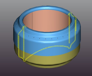 A 3-D view of a beverage-can stove with a cross-section in yellow.
 -
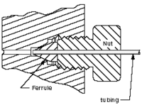 A 2-D cross-sectional view of a compression seal.
 -
 Cutaway of a Porsche 996
 -
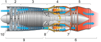 Cross-section of a jet engine
 -
 Section view in architectural design


_MET_DP801757_-_cropped.jpg)
Auxiliary views[edit]
An auxiliary view or pictorial, is an orthographic view that is projected into any plane other than one of the six primary views.[3] These views are typically used when an object has a surface in an oblique plane. By projecting into a plane parallel with the oblique surface, the true size and shape of the surface are shown. Auxiliary views are often drawn using isometric projection.
Multiviews[edit]
This article needs editing to comply with Wikipedia's Manual of Style. (April 2014) |
Quadrants in descriptive geometry[edit]

Modern orthographic projection is derived from Gaspard Monge's descriptive geometry.[4] Monge defined a reference system of two viewing planes, horizontal H ("ground") and vertical V ("backdrop"). These two planes intersect to partition 3D space into 4 quadrants, which he labeled:
- I: above H, in front of V
- II: above H, behind V
- III: below H, behind V
- IV: below H, in front of V
These quadrant labels are the same as used in 2D planar geometry, as seen from infinitely far to the "left", taking H and V to be the X-axis and Y-axis, respectively.
The 3D object of interest is then placed into either quadrant I or III (equivalently, the position of the intersection line between the two planes is shifted), obtaining first- and third-angle projections, respectively. Quadrants II and IV are also mathematically valid, but their use would result in one view "true" and the other view "flipped" by 180° through its vertical centerline, which is too confusing for technical drawings. (In cases where such a view is useful, e.g. a ceiling viewed from above, a reflected view is used, which is a mirror image of the true orthographic view.)
Monge's original formulation uses two planes only and obtains the top and front views only. The addition of a third plane to show a side view (either left or right) is a modern extension. The terminology of quadrant is a mild anachronism, as a modern orthographic projection with three views corresponds more precisely to an octant of 3D space.
First-angle projection[edit]

In first-angle projection, the object is conceptually located in quadrant I, i.e. it floats above and before the viewing planes, the planes are opaque, and each view is pushed through the object onto the plane furthest from it. (Mnemonic: an "actor on a stage".) Extending to the 6-sided box, each view of the object is projected in the direction (sense) of sight of the object, onto the (opaque) interior walls of the box; that is, each view of the object is drawn on the opposite side of the box. A two-dimensional representation of the object is then created by "unfolding" the box, to view all of the interior walls. This produces two plans and four elevations. A simpler way to visualize this is to place the object on top of an upside-down bowl. Sliding the object down the right edge of the bowl reveals the right side view.
-
 An image of an object in a box.
 -
 The same image, with views of the object projected in the direction of sight onto walls using first-angle projection.
 -
 Similar image showing the box unfolding from around the object.
 -
 Image showing orthographic views located relative to each other in accordance with first-angle projection.


Third-angle projection[edit]

In third-angle projection, the object is conceptually located in quadrant III, i.e. it is positioned below and behind the viewing planes, the planes are transparent, and each view is pulled onto the plane closest to it. (Mnemonic: a "shark in a tank", esp. that is sunken into the floor.) Using the 6-sided viewing box, each view of the object is projected opposite to the direction (sense) of sight, onto the (transparent) exterior walls of the box; that is, each view of the object is drawn on the same side of the box. The box is then unfolded to view all of its exterior walls. A simpler way to visualize this is to place the object in the bottom of a bowl. Sliding the object up the right edge of the bowl reveals the right side view.
Here is the construction of third angle projections of the same object as above. Note that the individual views are the same, just arranged differently.


Additional information[edit]

First-angle projection is as if the object were sitting on the paper and, from the "face" (front) view, it is rolled to the right to show the left side or rolled up to show its bottom. It is standard throughout Europe and Asia (excluding Japan). First-angle projection was widely used in the UK, but during World War II, British drawings sent to be manufactured in the USA, such as of the Rolls-Royce Merlin, had to be drawn in third-angle projection before they could be produced, e.g., as the Packard V-1650 Merlin. This meant that some British companies completely adopted third angle projection. BS 308 (Part 1) Engineering Drawing Practice, gave the option of using both projections, but generally, every illustration (other than the ones explaining the difference between first and third-angle) was done in first-angle. After the withdrawal of BS 308 in 1999, BS 8888 offered the same choice since it referred directly to ISO 5456-2, Technical drawings – Projection methods – Part 2: Orthographic representations.
Third-angle is as if the object were a box to be unfolded. If we unfold the box so that the front view is in the center of the two arms, then the top view is above it, the bottom view is below it, the left view is to the left, and the right view is to the right. It is standard in the USA (ASME Y14.3-2003 specifies it as the default projection system), Japan (JIS B 0001:2010 specifies it as the default projection system), Canada, and Australia (AS1100.101 specifies it as the preferred projection system).
Both first-angle and third-angle projections result in the same 6 views; the difference between them is the arrangement of these views around the box.
Symbol[edit]

A great deal of confusion has ensued in drafting rooms and engineering departments when drawings are transferred from one convention to another. On engineering drawings, the projection is denoted by an international symbol representing a truncated cone in either first-angle or third-angle projection, as shown by the diagram on the right.
The 3D interpretation is a solid truncated cone, with the small end pointing toward the viewer. The front view is, therefore, two concentric circles. The fact that the inner circle is drawn with a solid line instead of dashed identifies this view as the front view, not the rear view. The side view is an isosceles trapezoid.
- In first-angle projection, the front view is pushed back to the rear wall, and the right side view is pushed to the left wall, so the first-angle symbol shows the trapezoid with its shortest side away from the circles.
- In third-angle projection, the front view is pulled forward to the front wall, and the right side view is pulled to the right wall, so the third-angle symbol shows the trapezoid with its shortest side towards the circles.
Multiviews without rotation[edit]
Orthographic multiview projection is derived from the principles of descriptive geometry and may produce an image of a specified, imaginary object as viewed from any direction of space. Orthographic projection is distinguished by parallel projectors emanating from all points of the imaged object and which intersect of projection at right angles. Above, a technique is described that obtains varying views by projecting images after the object is rotated to the desired position.
Descriptive geometry customarily relies on obtaining various views by imagining an object to be stationary and changing the direction of projection (viewing) in order to obtain the desired view.
See Figure 1. Using the rotation technique above, note that no orthographic view is available looking perpendicularly at any of the inclined surfaces. Suppose a technician desired such a view to, say, look through a hole to be drilled perpendicularly to the surface. Such a view might be desired for calculating clearances or for dimensioning purposes. To obtain this view without multiple rotations requires the principles of Descriptive Geometry. The steps below describe the use of these principles in third angle projection.

- Fig.1: Pictorial of the imaginary object that the technician wishes to image.
- Fig.2: The object is imagined behind a vertical plane of projection. The angled corner of the plane of projection is addressed later.
- Fig.3: Projectors emanate parallel from all points of the object, perpendicular to the plane of projection.
- Fig.4: An image is created thereby.
- Fig.5: A second, horizontal plane of projection is added, perpendicular to the first.
- Fig.6: Projectors emanate parallel from all points of the object perpendicular to the second plane of projection.
- Fig.7: An image is created thereby.
- Fig.8: The third plane of projection is added, perpendicular to the previous two.
- Fig.9: Projectors emanate parallel from all points of the object perpendicular to the third plane of projection.

- Fig.10: An image is created thereby.
- Fig.11: The fourth plane of projection is added parallel to the chosen inclined surface, and perforce, perpendicular to the first (Frontal) plane of projection.
- Fig.12: Projectors emanate parallel from all points of the object perpendicularly from the inclined surface, and perforce, perpendicular to the fourth (Auxiliary) plane of projection.
- Fig.13: An image is created thereby.
- Fig.14-16: The various planes of projection are unfolded to be planar with the Frontal plane of projection.
- Fig.17: The final appearance of an orthographic multiview projection and which includes an "Auxiliary view" showing the true shape of an inclined surface.
Territorial use[edit]
First-angle is used in most of the world.[5]
Third-angle projection is most commonly used in America,[6] Japan (in JIS B 0001:2010);[7] and is preferred in Australia, as laid down in AS 1100.101—1992 6.3.3.[8]
In the UK, BS8888 9.7.2.1 allows for three different conventions for arranging views: Labelled Views, Third Angle Projection, and First Angle Projection.
See also[edit]
- Architectural drawing
- Cross section (geometry)
- Engineering drawing
- Graphical projection
- Plans (drawings)
References[edit]
This article needs additional citations for verification. (November 2009) |
- ^ Ingrid Carlbom, Joseph Paciorek (1978), "Planar Geometric Projections and Viewing Transformations", ACM Computing Surveys, 10 (4): 465–502, CiteSeerX 10.1.1.532.4774, doi:10.1145/356744.356750, S2CID 708008
- ^ Ching, Frank (1985), Architectural Graphics - Second Edition, New York: Van Norstrand Reinhold, ISBN 978-0-442-21862-1
- ^ Bertoline, Gary R. Introduction to Graphics Communications for Engineers (4th Ed.). New York, NY. 2009
- ^ "Geometric Models - Jullien Models for Descriptive Geometry". Smithsonian Institution. Retrieved 2019-12-11.
- ^ "Third Angle Projection". Archived from the original on March 4, 2016. Retrieved December 10, 2019.
- ^ Madsen, David A.; Madsen, David P. (1 February 2016). Engineering Drawing and Design. Cengage Learning. ISBN 9781305659728 – via Google Books.
- ^ "Third Angle Projection". Musashino Art University. Retrieved 7 December 2016.
- ^ "Full text of "AS 1100.101 1992 Technical Dwgs"". archive.org.
BS 308 (Part 1) Engineering Drawing Practice BS 8888 Technical product documentation and specification ISO 5456-2 Technical drawings – Projection methods – Part 2: Orthographic Representations (includes the truncated cone symbol)