
Coupling (train)

Couplings are used on railways to connect vehicles to form pulling or shunting units. They transmit tensile and compressive forces either via separate or integrated devices. For this reason and because pressure forces also play an important role in rail operations, unlike road traffic, the different types of construction are summarized under the term pulling and buffing device . Vehicles that travel between networks with different coupling standards are designed for the installation of several coupling types and converted at the transition or used as coupling wagons.
Screw coupling

The most widespread coupling on railways in Europe is the screw coupling . It contains a centrally arranged draw hook on each vehicle front side, to which the "coupling chain" is attached with a bolt. It consists of two brackets that are attached to the left and right of the drawbar with a bolt and are hinged to a nut at the other end. One end of the spindle is screwed into this nut, on the other end of which a nut is screwed, which is connected to the tension yoke in an articulated manner. Both round threads are in opposite directions , so that the dome chain can be charged by simply rotating the spindle and relaxed. This 35 kg coupling chain is folded back under the towing hook when not in use and hooked into a hook on the undercarriage of the vehicle with the pulling bracket.
For coupling, the pulling yoke is unhooked from the hook on one vehicle and inserted into the pulling hook of the other vehicle. The coupling chain is then shortened by turning the spindle. So that the spindle can be turned, there is a foldable handle in the middle, the handle. When the desired shortening has been achieved, the handle is inserted into the handle lock, a small hook on the nut that connects the two brackets. The handle lock prevents the spindle from turning during operation and thereby loosening the coupling.
Although two tow hooks and two couplings are always available between two vehicles, only one tow hook and one coupling are used for coupling. The unused parts serve as a reserve and ensure that the vehicles can still be coupled even after a coupling has broken. The tabs are the weakest link and are intended as a predetermined breaking point. Vehicles that are rarely coupled to each other, such as railcars, sometimes only have one tow hook. If these vehicles were to be coupled to one another, emergency couplings were available, which consisted of the spindle and two tie bars.
Because the screw coupling can only transmit tensile forces, vehicles must always have spring buffers that can absorb the impact and pressure forces between the vehicles, such as those that occur when braking. When coupling the vehicles, it is usually ensured that the buffers are pressed in slightly when the train is stationary. This is achieved by the locomotive, the carriage presses until the clutch placed in the draw hook and the spindle is tightened.
The screw coupling requires one person to couple or uncouple each vehicle by hand. This takes at least a minute, since the main air line , and in the case of passenger coaches, the main air reservoir line , the train busbar and additional electrical lines must also be connected. The work - between the buffers and with the grease-lubricated clutch - is also a very dirty affair. When changing locomotives (e.g. in terminal stations), a shunting worker must therefore always be present or the driver must first change. In European railway vehicles with screw couplings, the working space to be kept free around the coupling is standardized as the Bern area .
In the case of shunting locomotives, special devices are sometimes used to make coupling easier. There are devices that engage directly in the tow hook of the vehicle to be coupled, but also those that lift the coupling of the shunting locomotive and place it in the tow hook of the vehicle to be coupled.
In the standard-gauge railways in Europe including Asia Minor and North Africa , a uniform arrangement of screw couplings and buffers, which was originally used in Great Britain and North Germany, assured the transition capability of the wagons. The regular dimension of the height of the draw gear and the middle of the buffer above the upper edge of the rail ("buffer stand") is then a maximum of 1065 and at least 940 millimeters, the buffer spacing 1750 millimeters. Because of the straightforward introduction of forces into the long girders, particularly in the case of two-axle wagons for Iberian and Indian broad gauge, a larger buffer distance of 1950 millimeters was introduced in the networks concerned. Wagons designed for alternating traffic between the regular and Iberian broad-gauge network were equipped with wider buffer plates to compensate for this until the 1990s. The French Corail wagons were practically all equipped with these extra-wide buffer plates. In Spain, the regular size of the buffer spacing was adapted to the European standard before the turn of the millennium, but there are still a few vehicles with the old buffer spacing in use. In the case of narrow-gauge railways, on the other hand, different arrangements have become established, for example with a central buffer and a screw coupling underneath (e.g. often in France, on the Montreux-Berner Oberland Railway ), with a central buffer and screw couplings attached to both sides (e.g. Rhaetian Railway , Rügensche) Kleinbahn and Harz narrow-gauge railway , so-called balancing lever or compensating coupling) as well as with central screw coupling and side buffers, but different distances and heights than the standard gauge (for example with the Tunisian Gafsabahn and today in the Tunisian meter- gauge network in general).
Shunting coupling

A shunting coupling is a special automatic coupling that is usually attached to shunting locomotives and can be controlled by the shunting engineer. No manual coupling process is necessary, especially with conventional screw couplings, as the maneuvering coupling can automatically grip the towing hook and release it again. For faster processing, the connection of the main air line couplings is dispensed with in shunting operations, if the braking capacity of the locomotive, the masses to be moved and the inclination conditions permit ; the shunting coupling does not allow the brake or electrical connections to be automatically connected.
In a more distant sense, the coupling rods between two-way vehicles in shunting operations and railroad cars also belong to the shunting couplings.
Keller's coupling
The Keller clutch was a clutch for push locomotives named after the secret building officer Wilhelm Keller of the Aachen machine inspection . It had been in use since around 1900 and was an invention to enable pushing locomotives that are supposed to leave the train to be pushed while it was in motion to be coupled to it anyway. The Keller coupling can be released from the driver's cab of the sliding locomotive while driving. Their use requires structural preparation of the locomotives intended for being pushed, in particular the release cable must be laid.
construction

In principle, the Keller coupling is constructed like a screw coupling and is also hooked into the tow hook of the pushing locomotive and the end car of the unit to be pushed. The only difference to it is that it is not contractible and is not permanently connected with a coupling hook.
It consists of the suspension eyelet (part 1), the intermediate eyelet (part 2) and the pivot pin fork (part 3). When using the coupling, the suspension eye is hooked into the towing hook of the pushing locomotive and the pivot pin fork is hooked into the towing hook of the end carriage of the pushing unit. The pivot pin (part 4), which holds the coupling on the final carriage in the draw hook, and the spring-loaded locking bolt (part 5), which prevents the pivot pin from swiveling out, are arranged in the pivot pin fork. The pull lever (part 6) is connected to the locking bolt and pulls the locking bolt back from the pivot bolt when it is turned against spring force. The pull lever is controlled from the driver's cab of the push locomotive with the pull rope (part 7).
function
To use the Keller coupling, the suspension eye (part 1) is hooked into the towing hook of the push locomotive. After this has moved up to the unit to be pushed in, the shunter hooks the pivot pin fork (part 3) into the draw hook of the end carriage of the unit to be pushed in. The push locomotive is not connected to the main air line of the train to be pushed in, both the push locomotive and the train to be pushed in must carry end-of-train signals . The shunter then notifies the driver of the push locomotive that the clutch is being used properly. The push locomotive is thus connected to the train unit, can also be pulled in certain sections and does not accidentally lose contact with the train.
If the pushing forward is usually to be ended at the point indicated by the signal Ts 1 ( stop pushing ), the driver of the pushing locomotive must ensure that the clutch is released. He pulls on the pull rope (part 7), then the pull lever (part 6) moves from the vertical to the horizontal position. As a result, the locking bolt (part 5) moves against the spring force and releases the pivot bolt (part 4). Now the driver of the sliding locomotive reduces the speed, the pivot pin slides out of the draw hook of the end car and the Keller coupling falls down. The driver of the push locomotive notices this on the slack pulling rope in the driver's cab.
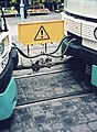
The Keller'sche clutch is not used in push operation if the push locomotive remains on the train after the uphill journey, in order to brake the entire unit during the subsequent descent using the dynamic or regenerative brake , in steam operation with the Riggenbach counter-pressure brake or up to one The train stops as scheduled. In this case, the push-pull locomotive is connected to the train to be pushed with the regulating screw coupling and connected to the main air line of the train. In this case, if the coupling chain of the last car cannot be used, the Keller coupling is hung under the right-hand buffer of the sliding locomotive without any function. A photo of a sliding locomotive after the train was separated by the Keller coupling can be seen in the same book on page 188.
Close coupling
In individual cases, close couplings are also used in order to minimize the loss lengths with standard couplings.
Central buffer coupling
Central buffer couplings are combinations of buffers and couplings on rail vehicles .
Hand-coupled central buffer couplings

In narrow-gauge cars and trams hand-operated central buffer couplings are very often used. In these, either a central connecting piece is inserted into both coupling receptacles and pinned with bolts ( trumpet coupling or funnel coupling ) or the coupling receptacles opposite one another have mirror-image arrangements of laterally interlocking through-holes which are also secured with bolts ( Albert coupling ). An alternative generic term is a pin coupling . Such clutches are connected to spring damping elements on the vehicle side , which are structurally derived from the pure buffers .
Examples of further manually operated central buffer couplings:
- Balancing lever or compensating coupling (used worldwide on narrow-gauge railways)
- Bosna coupling (on narrow-gauge railways in Austria, Hungary and the Balkans)

Albert coupling
Albert coupling, coupled

The central buffer coupling with transmission of the tensile force by means of chains (Balancierhebel- or compensating coupling), Frankfurter Feldbahnmuseum 2007

Hopper coupling of the Saxon narrow-gauge railways

Bosna coupling in coupled condition


Automatic central buffer couplings
In order to avoid the work involved in coupling and the resulting risk of accidents, efforts were made at the end of the 19th century to introduce an automatic ( automatic ) combined buffer and coupling device . In the USA , the manual clutch previously used was replaced nationwide by the Janney clutch as early as 1893 . In the Soviet Union , too, a similar type was introduced as type SA3 from 1932 based on the Willison type, which was also developed in the USA . Compared to the Janney coupling, this has the advantage that it is always ready for coupling and does not have to be unlocked manually. Both types SA3 and Janney are unstable in their original design, the domes can move each other in height. An automatic coupling of compressed air and electrical connections is not possible. The Janney type has been expanded to form a rigid coupling with side rigging elements and an additional vertical swivel range, especially for passenger coaches and railcars. This made it possible to supplement the coupling with line couplings.
In the 1960s, work began on developing a UIC central buffer coupling in order to create such a coupling system for standard-gauge railways in Europe. The UIC coupling should also couple two compressed air and electrical lines and it should be possible to couple with type SA3 without an adapter. As a result of the extensive and costly developments, a system of a supplemented SA3 coupling (see AK69e ) was ready for use and production in 1970. The rigging organs, in which the line couplings are integrated, were arranged under the Willison profile. However, it was not possible to agree on a changeover, whereby the requirement to convert the entire vehicle fleet within an extremely short period of time in order to avoid complicated mixed domes also played a role. The mixed coupling, which was co-developed from the start, was only approved for maneuvering at the time. Too many railways were unable to finance the changeover. The project was stopped in 1985, the fall of the Iron Curtain and the subsequent re-integration of pan-European rail transport postponed an agreement again. The majority of European railway companies therefore still use the screw coupling, although the mixed coupling has proven itself for decades on train journeys in Finland and also on journeys with ore wagons. However, the automatic central buffer coupling is used for special cases, for example for the heavy ore trains of the DB from the seaports to the steelworks and on the Kiruna – Narvik ore railway , as well as the SBB's III standard car . The C-AKv coupling is the latest state of development for the pan-European standard gauge network . As in the case of the rigid Janney types, the rigidifying organs are located on the side of the dome head, the line couplings are integrated into the Willison profile. This coupling also allows coupling with SA3 and previous UIC central buffer couplings as well as with screw couplings without a loose mixed coupling.
In a 2015 study, the cost of an automatic clutch was estimated at 5,000 to 38,000 euros per car. This is offset by the cost of a screw coupling of 3000 euros.
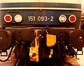
A utomatic K upplung AK69e at a Erzzuglok the series 151

Central buffer coupling type Janney

SA3 coupling, top view

C-AKv central buffer coupling


Semi-automatic and automatic central buffer couplings for multiple units and special uses
In addition to the automatic coupling of the mechanical connection, modern semi-automatic and automatic central buffer couplings can usually also automatically establish the connection of the brake lines and electrical control lines; the train busbar is also rarely coupled. Couplings that create the connections automatically when starting up, but which have to be separated by hand, are called semi-automatic couplings. With automatic couplings, uncoupling can also be carried out remotely by the engine driver without leaving the driver's cab. With the use of automatic couplings, trains in stations can be easily separated and reunited so that the train can either be adapted to the required capacity or different destinations can be served with wing trains. The Scharfenberg coupling type 10 is often used in high-speed railcars in particular, it is standardized within the framework of the TSI .

Scharfenbergkupplung on a railcar of the DB Class 612

+ GF + tram coupling (GFT)

+ GF + branch line coupling (GFN)

+ GF + - suburban railway coupling (GFV)

BSI compact clutch , here at a car of the tram Bielefeld


Germany
In Germany , after 1996 with the division of the business areas, a division of the vehicle fleet took place at Deutsche Bahn AG . In this context, the opportunity arose for passenger transport to acquire all multiple units with Scharfenberg couplings by modernizing the vehicle fleet . It is mainly used on multiple units (e.g. S-Bahn , ICE ); however, it is not suitable for heavy freight trains as no high tensile forces can be transmitted. In some cases, there are also lower tractive forces between coupled multiple units because some individual multiple units have their own drive. Often, however, the different series are only limited (only the mechanical and air coupling can be coupled, the electric coupling cannot be coupled) or cannot be coupled at all. (E.g. different versions of the Alstom LINT ; during a coupling process, the electrical coupling would be damaged by a steel bracket.)
Various narrow-gauge and rack-and-pinion railways, such as the narrow-gauge railways in Saxony, use simple forms of the Scharfenberg coupling (often without electrical connections) as a general coupling for all vehicle types, which does not pose any problems due to the lower train weights.
In March 2019, the Federal Ministry of Transport announced the development of a migration concept for the EU-wide introduction of a so-called "digital automatic coupling".
Switzerland
In Switzerland , the formerly semi-automatic + GF + coupling ( Georg Fischer AG , Schaffhausen ), today Faiveley Transport Schwab AG, which was presented in 1914 at the national exhibition in Bern , is mostly used on narrow-gauge and tram railways . This coupling is available in two versions, as the tram type for tram and light branch lines and in the heavier and wider branch line design, so-called funnel heads. Both have the same function, but cannot be coupled to one another due to their different widths. The fully automatic version for suburban railways is except for Swiss private railways and the SBB u. a. also in use in Belgium and Finland.
Fully automatic Schwab couplings ( Schwab Verkehrstechnik AG , Schaffhausen), the successor product of GF couplings, are mostly used in new Stadler multiple units. As with the GF couplings, there are three different variants for main railways (FK-15-10), new (FK-15-12), metros / branch lines (FK-9-6) and trams (FK-5.5-4 and FK -3-2.5), which cannot be coupled with one another or with the GF couplings. The Scharfenberg coupling type 10, also available from Schwab, has so far only been installed on exported vehicles. All types are rigid central buffer couplings that also couple the compressed air lines for the train brake and can be equipped with contact attachments for electrical connections.
Hybrid clutches
Quickly adaptable multiple couplings were developed early on for operation with vehicles with different equipment. One of the first designs was foldable Janney couplings on British passenger coaches in conjunction with extendable buffers. The central buffer coupling head is suspended in the eye of the draw hook; in the operating position it also rests in the draw hook mouth with a bolt to be inserted. The drawbar shaft is reinforced for the introduction of the compressive forces, the floor frame of the affected vehicles is designed for the introduction of compressive forces in the central axis. Instead of the drawbar, as in vehicles equipped exclusively with central buffer couplings, there is a receptacle designed for tensile and compressive forces. In addition to the suspension, the buffers can be pulled out; in the active position, they are locked in place with spacers.
A comparable design was also created for couplings with a Willison profile such as the SA-3 type. However, it did not become more widespread, as the Unilink type has been a better solution with an integrated coupling chain since the 1990s . It is used, for example, in Finnish locomotives and Turkish self-unloading wagons for transporting coal and ore. A similarly arranged coupling chain is also part of the system with the C-AKv coupling .
The version of the CargoFlex coupling for locomotives, which corresponds to a reinforced version of the Scharfenberg coupling type 10, also contains an integrated screw coupling chain . To use it, the dome head is folded up by 90 °. In 2018, SBB fitted twelve Re 4/4 II locomotives with couplings of this type.

Mark I generator car with a foldable Janney dome head

Unilink coupling head with integrated screw coupling chain

Cargoflex hybrid coupling on the Re 420 288 locomotive


literature
- Wolfgang Glatte: domes at the push of a button. The shunting coupling. In: LOK MAGAZINE . Number 261, volume 42, 2003. GeraNova Zeitschriftenverlag, Munich, ISSN 0458-1822 , pp. 48–51.
- Automatic coupling systems in rail transport . In: Your train . No. 9 , 2019, ISSN 0948-7263 , p. 17-22 .
Web links
- Dr. Reiner Seibt: The automatic central buffer coupling , extensive information on the development of the European central buffer coupling
- The shunting coupling of the Kö 0128
Individual evidence
- ^ Kilian T. Elsasser: The introduction of the automatic coupling requires long-term planning. (PDF; 498 kB) Accessed March 10, 2013 .
- ↑ Bruno Lämmli: Couplings are important. In: lokifahrer.ch. Retrieved March 10, 2013 .
- ↑ Semi-automatic screw coupling ZSS-2006 type L650. (No longer available online.) Formerly in the original ; Retrieved March 10, 2013 . ( Page no longer available , search in web archives ) Info: The link was automatically marked as defective. Please check the link according to the instructions and then remove this notice.
- ↑ Manfred Weisbrod, "The Cellar Coupling", Eisenbahn-Journal 11/1996, page 10
- Jump up ↑ Lüdecke, "The series 96", EK-Verlag Freiburg 1991, ISBN 3-88255-831-8 , page 94
- ^ Places Lüdecke, "The Series 96", EK-Verlag Freiburg 1991, ISBN 3-88255-831-8 , p. 188
- ↑ BMVI is examining migration strategies for automatic coupling . In: Railway technical review . No. 5 , May 2019, ISSN 0013-2845 , p. 6 .
- ↑ Creation of a concept for the EU-wide migration of a digital automatic coupling system (DAK) for rail freight transport. In: evergabe-online.de. Procurement Office of the Federal Ministry of the Interior, March 19, 2019, accessed on May 18, 2019 .
- ↑ Schweizerische Bauzeitung Volume 66, Number 16, Automatic coupling for branch line vehicles http://www.e-periodica.ch/digbib/view?pid=sbz-002:1915:65:66#2589