
Reactive power compensation
With reactive power compensation ( PFC ), also known as reactive current compensation , the undesired displacement reactive power and the associated reactive current from electrical consumers is reduced in AC voltage networks . The reactive power compensation is done by compensating inductive or capacitive reactive power by means of capacitive or inductive loads. It is compensated with capacitors or filter circuit reactors.
Basics
Reactive power and the reactive current required for it are required to generate electrostatic or electromagnetic fields . Since these fields continuously build up and decrease in time with the alternating voltage, the energy oscillates continuously between the generator and the electrical consumer. This cannot be used or converted into another form of energy , together with the active power as apparent power, it loads the power supply network and the generating systems ( generators , transformers ).
Uncompensated reactive power requires larger (synchronous) generators. If the reactive power is high, additional magnetically overexcited synchronous generators may only be required for compensation. Most of the generators are synchronous generators that can compensate reactive power in "phase shifter" mode, but only very few electrical consumers are equipped with capacitive devices for reactive power compensation.

In larger systems, the sum of the individual mismatches can become large and overload the general power grid.
Usual energy meters only record active energy. For this reason, special meters for measuring reactive energy are primarily installed at large commercial customers in order to allocate the resulting costs.
Above a certain size, the constant costs justify the installation of an out-of-phase consumer, the reactive power compensation system . This is connected to all inductive consumers at the central feed point. Its counteracting reactive power is, if possible, of the same size as the installed inductive reactive power. This measure is called compensation .
A static system consists of permanently installed or automatically switched capacitors (active reactive power filters), which absorb a capacitive reactive current that is directed opposite to the usually inductive reactive current of the consumer and cancels it by approx. 95%. If the inductive reactive power were to be fully compensated, the capacitive and inductive loads would only cancel each other out for a certain load condition, but would again load the network with a lower load due to capacitive overcompensation. Capacitive reactive power is generally associated with overvoltages and technical control difficulties, which is why it is avoided.
Theoretical consideration

Electrical consumers in the low-voltage network are mostly ohmic-inductive , i. This means that the consumers need a magnetic field and draw inductive reactive power. Reactive power compensation requires the parallel connection of capacities , which in turn draw capacitive reactive power. A series connection with the consumables is not advisable, as this would create a series resonant circuit that results in a reactive current short circuit near its resonance frequency .
However, this does not apply to devices with known data, where exact compensation is possible (example: duo switching with fluorescent tubes).
Reactive power with current without harmonics
The following consideration relates to sinusoidal voltage and consumables with sinusoidal and therefore harmonic-free power consumption. Due to the compensation system, the reactive current mostly only shuttles between the consumables and the compensation system. The supply network is relieved.
The relevant for the load on the supply network size of the apparent power S is the geometric sum of active power P and reactive power Q . According to DIN 40 110-1, these are linked to one another as follows:


The total reactive power of the compensated consumer is made up of the inductive reactive power and the capacitive reactive power .


The inductive reactive current and the capacitive reactive current are phase shifted by 180 ° and thus have opposite signs of the instantaneous values. According to the definition that the phase shift angle φ is positive for inductive loads , one also defines positive; conversely, φ and are negative for capacitive loads . By adding the correct sign, the total reactive power is always lower than each of the amounts of the individual reactive powers.
The reactive power component is usually based on a power factor, which is the same in this case , of about


- (inductive)

compensated. In the case of motor systems with asynchronous machines there is otherwise the risk of self-excitation if the reactive power is fully compensated. In the case of self-excitation, when the power supply is disconnected, the motor becomes a generator , and dangerous overvoltages can occur. This case is also known as the resonance case.
With the same active power, a consumer loads the supply line with a proportionally reduced current strength if its reactive power is compensated according to the power factor . The Joulean conduction losses decrease with the square of this ratio. Example: If the power factor is increased from to , the losses mentioned decrease by 40%.


Another approach is to make the complex load impedance purely real by adding a reactance so that becomes. The dimensions of the corresponding compensation component can then also be calculated using this condition in the form of a homogeneous equation.


Furthermore, due to the fluctuating load on a consumable, complete compensation cannot often be carried out with simple capacitors or coils . For this purpose, active power factor correction elements or so-called "network management systems" are used, which provide the required amount of reactive power at any time.
With particularly large amounts of reactive power in energy supply systems, reactive power generators are occasionally used. These are synchronous generators which, depending on the state of excitation, can emit inductive or capacitive reactive power. They are also known as rotating phase shifters or synchronous phase shifters .
The current state of the art, however, is the use of static reactive power compensators close to the inductive consumer or line section. These are combinations of capacitances and inductances that are arranged parallel to the load to be compensated or to the network section to be compensated. The current flow in the individual components is regulated by thyristor valves and thus the degree of reactive power compensation. Compared to the rotating phase shifter, this has the advantage that there is no wear on the system, and a static compensator enables dynamic control of load fluctuations.
Reactive power for current with harmonics
The above relationships only apply to sinusoidal curves for voltages and currents, which is generally only the case for linear networks. If there are non-linear components in a circuit, such as magnetically saturating inductances or power supplies with rectifiers , the current is distorted, i.e. i.e. it contains harmonics . In addition to the reactive power Q of the fundamental oscillation , there is a distortion reactive power D , which summarizes the reactive power components of the harmonics.
The reactive power compensation by means of compensation filters connected in parallel, such as capacitors, is only possible with one frequency, usually with the frequency of the fundamental as the mains frequency . The reactive power of the other oscillations is over- or under-compensated. This can be remedied by power factor correction filters, which are connected in series with the non-linear consumer and either dampen the harmonics using suitable filter structures or artificially simulate a sinusoidal current curve on the network side using electronic circuits . This allows the power factor to be brought close to 1.
- Current and voltage curves for harmonics

Clearly non-linearly distorted current curve (blue) with a power factor of 0.75
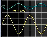
Compensated to a power factor of 1 by power factor correction filters


example


The parallel connection of a resistor and a capacitor, shown opposite, is connected to the 230 V power supply; the specified currents flow at 50 Hz. 2.3 A active current flows through the resistor, the connection cable must be rated for the total current of 2.72 A due to the reactive current of 1.45 A. In addition to the active power of 529 W, there is a reactive power of 334 VAr , which indicates how much energy per time oscillates between generator and capacitor and unnecessarily loads cables and transformers.
To compensate for this reactive power, a suitably selected inductance of 0.5 H is connected in parallel to the device, the reactive current of which is also 1.45 A. The reactive currents of the capacitor and coil compensate each other due to their opposite phase positions, and the total current consumption drops to 2.3 A. Ideally , the parallel connection of the coil and capacitor represents a parallel resonant circuit that does not draw any reactive current from the generator at 50 Hz. Because P = R line · I ², the power loss in the supply lines drops to 100% · (2.3 / 2.72) ² = 71% of the original value.
Use of reactive power compensation systems
Reactive current causes ohmic losses in lines and transformers. The losses are paid indirectly to the energy supply company via the network usage fees ( Section 10 Electricity Network Fee Ordinance ).
The size of the transformer determines the maximum apparent power that can be drawn. If the proportion of reactive power is high, correspondingly less active power can be drawn. A compensation system saves an expansion of the transformer and possibly cables.
For bulk buyers (special contract customers), the reactive energy is also measured and calculated in the electricity bill. There is therefore a monetary incentive to keep the performance factor within certain limits (e.g. ). With a reactive current compensation system, these additional costs are ideally eliminated.

Audio frequency locks
When using reactive current compensation in a network with a ripple control system, it may be necessary to use audio frequency barriers to prevent the ripple control signals from being blocked from the network by the compensation capacitors . For this purpose, the capacitors are provided with small chokes, which are almost ineffective at line frequency.
Others
The generator of modern wind turbines ("wind turbines") or typical inverters of photovoltaic systems are decoupled from the power grid via a direct current intermediate circuit. It is also possible to regulate the phase shift between voltage and current in the three-phase alternating current (three-phase current) fed in. These systems no longer load the grid with reactive power ; on the contrary, they are even used for reactive power compensation.
literature
- Günter Springer: Expertise in electrical engineering. 18th edition, Verlag - Europa - Lehrmittel, 1989, ISBN 3-8085-3018-9
- Réne Flosdorff, Günther Hilgarth: Electrical energy distribution. 9th edition, Verlag BG Teubner, 2005, ISBN 3-519-36424-7
- Wolfgang Just, Wolfgang Hofmann: Reactive Current Compensation in Operating Practice. 4th edition, VDE-Verlag, 2003, ISBN 3-800-72651-3