
Synchronous machine
A synchronous machine is a rotating electrical machine in which the rotor (also: runner ) runs synchronously with the rotating field of the stator . Synchronous machines are often designed as three-phase machines , i.e. as three-phase synchronous machines . In principle, any synchronous machine can be operated as an electric motor and generator . Synchronous generators are used in the energy industry to provide electrical energy in a wide range of capacities . Synchronous motors are used in many different ways as drive machines in industry, for example as drives for ships and trains or for pumps and compressors .
The synchronous machine got its name because of the operating characteristic that its rotor rotates exactly synchronously with the rotating field specified by the mains frequency . This distinguishes synchronous machines from asynchronous machines , the rotor of which leads the rotating field in motor operation and in generator operation. Another distinguishing feature is that, in contrast to asynchronous machines, an excitation field is required to operate synchronous machines . Before a synchronous machine is connected to the grid as a generator, it must be synchronized with the grid after an asynchronous start- up. In generator mode, the machine generally runs at a relatively constant speed. Synchronous motors, on the other hand, often have to be variable in their speed. In order to be able to regulate the speed of a synchronous motor steplessly, power electronics such as B. a frequency converter is used. A rotary encoder (line encoder, resolver ) constantly records the change in the rotor position during operation. The control electronics use this to determine the actual speed. When loaded, the rotor of the synchronous motor follows the rotating field in the load-dependent rotor angle . In generator mode, the rotor angle is positive in the direction of rotation, so it leads. Synchronous machines can absorb or output reactive power . This means that the machine can also be used for reactive power compensation . The reactive power behavior can be influenced by the excitation .

history
As a forerunner of the three-phase synchronous machine, the single-phase alternating current generator was used to supply lighting systems from the middle of the 19th century . In 1887 Friedrich August Haselwander and the American Charles Schenk Bradley developed the three-phase synchronous generator independently of one another. During the developments, the salient pole and full pole machine designs emerged. A co-founder of Brown, Boveri AG , Charles EL Brown , is considered to be the inventor of the roller rotor, with the excitation winding distributed in grooves on the circumference.
The further development of the synchronous machine was closely related to the expansion of the electrical energy supply in the context of electrification and the need for increasingly powerful generators. First, single pole or salient pole machines were created , as these were suitable for generating electricity with the slow-running piston steam engines as the drive machine. When the steam turbines replaced the piston steam engines, the high-speed, cylindrical solid pole rotors were used. The synchronous machine is of great importance in the provision of electrical energy. In large power plants such as coal or nuclear power plants and in gas turbine power plants of all sizes, synchronous generators are used almost exclusively. The importance of the synchronous machine in this area will, however, decrease in the future, as further developments in the field of regenerative energies mean that systems with smaller individual outputs such as wind turbines and thus alternative machine types will be used. In addition, synchronous machines or other machine types are not required at all for certain methods of energy supply, such as in photovoltaic systems .
Irrespective of this, synchronous machines have always been used in industry when a constant drive speed or phase shift operation was required.
construction
Synchronous machines are designed in various designs. They are manufactured as external or internal pole machines . Both machine types have in common that, like all three-phase machines, they have a rotor and a stator. In any case, an excitation device is required for the operation of the machines. In addition, there is another division into salient pole and full pole machines.
Internal pole machine


Stator
The stator winding consists of three winding phases offset by 120 ° / p ( p = number of pole pairs ), which are designated with U, V and W. They are connected in star or delta connection. In generator mode, electrical energy is fed into the network via the stator winding, or it is drawn from the network in motor mode. The structure of the stator is the same as that of the three-phase asynchronous machine . The stator of the internal pole machine is also called an armature and the stator winding is accordingly called an armature winding. The armature of the synchronous machine is not to be confused with the armature of the DC machine , in which the rotor is called the armature.
Rotor
The rotor of the internal pole machine can be designed as a salient pole rotor or a full pole rotor. Rotor , pole wheel and, more rarely, inductor are also the names for both types of rotor. The full pole rotor is also referred to as a roller rotor and a full drum rotor. This has a rotationally symmetrical structure and carries the excitation winding . The excitation winding is inserted into the slots of the solid pole rotor and secured with slot wedges. Thigh pole runners have pronounced pole pieces and legs, which is why they have a large diameter. The excitation winding is wound on the armature's legs.
Excitation
There are several principles of excitation, such as static excitation . With this principle, the ends of the excitation winding are brought out via slip rings on the rotor shaft. The excitation voltage is applied to the excitation winding via carbon brushes . Another principle is brushless excitation via external pole synchronous generators and rotating diode rectifiers (so-called RG sets ). However, due to the increasing dynamic requirements (pendulum damping device, Power System Stabilizer , PSS), this technology is only rarely used in new power plants because RG excitations react much more slowly than slip ring excitations. If it is a permanent magnet synchronous machine (PSM), the rotor carries permanent magnets for excitation. The permanent magnet excitation is becoming increasingly important. The hybrid synchronous machine (HSM), on the other hand, combines the effect of electromagnetic reluctance and the effect of permanent magnets to generate torque.
Damper winding (damper cage)
Larger synchronous machines have a damper winding (damper cage). It affects the operating behavior of synchronous machines. In the case of full-pole machines, the damper winding sits in the slots of the exciter winding or in separate damper slots between these slots. In salient pole machines, the damper winding sits in separate damper grooves in the pole shoes. The damper winding in full-pole machines is basically similar to the structure of the squirrel-cage rotor of an asynchronous machine . However, depending on the design, synchronous machines without a damper winding can have their own damping, which also has an effect on operation.
The most important task of the damper winding of synchronous machines is to dampen mechanical oscillating torques. Oscillation torques occur as a result of asynchronous operation, machines coupled to the synchronous machine with periodic torque (e.g. internal combustion engines as drive machines or piston compressors as work machines) and load surges. In asymmetrical operation (unbalanced load ) and in extreme cases in single-phase operation, an inverse rotating field occurs, which is also damped. If not damped, the inverse rotating field would result in high losses.
The attenuation of the inverse fields is particularly important for generator operation. Inverse fields cause a current in the damper winding, the frequency of which is twice as high as the mains frequency. The damper winding is designed with low resistance in order to keep the losses low.
When the engine is running, it is primarily oscillating moments that have to be dampened. When loaded with a constant load torque, there is a balance between the torque required by the load and the torque supplied by the machine at a constant rotor angle (see also the spring model of the rotor angle of a synchronous machine ). A sudden increase in the load torque (load shock) delays its rotary motion beyond the rotor angle due to the rotor's mass moment of inertia. The load torque is now smaller than the motor torque and that in turn causes acceleration up to a rotor angle that is too small due to the mass moment of inertia. This oscillation is repeated with ever smaller amplitudes until equilibrium is reached again. The relative movement between the stator rotating field and the rotor generates a torque based on the principle of an asynchronous machine, which counteracts the pendulum movements. Solid parts of the rotor also have a similar effect, such as the solid rotor ball of the full pole machine or the solid pole shoes of the salient pole machine. This means that a certain damping can also take place without a damper winding. In addition to damping pendulum torques, the damper winding can also be used for self-starting based on the principle of an asynchronous motor with a squirrel cage.
Design depending on the rated speed
Full pole machines are operated at high speeds and are therefore well suited for use as turbo generators . The rotors of these generators are called turbo rotors . They are a few pairs of poles run and run at 50 Hz mains frequency up to 3000 min -1 . Due to the high speeds and the forces acting on the rotor, these generators have to be built slim and cannot idle because of the risk of overspeed. The size of full pole machines is limited in diameter by the centrifugal force limit and in length by the deflection limit.
Salient pole machines are often used as low-speed generators with large diameters and short lengths. They are designed with a large number of pole pairs and run at speeds of 60 to 750 min −1 .
External pole machine

In the stator of the external pole machine there are pronounced pole shoes and legs that carry the field winding. The three-strand rotor winding is located on the rotor, also called the armature in the case of the external pole machine. The ends of the rotor winding are brought out via slip rings. Carbon brushes take the provided power in generator mode or supply the required power in motor mode. This type of construction is not suitable for machines with a large rated power, as the currents increase depending on the power. Associated with this are the increase in losses in the slip ring apparatus and the need to make the slip ring apparatus larger in order to be able to carry the currents. Internal pole machines are used for high outputs.
Design of the windings
The windings of generators must be designed for the magnitude of the currents that occur in the event of a short circuit. This also applies to the excitation winding, since high current peaks also occur in it in the event of a short circuit. The highest short-circuit current occurs with a three-pole terminal short-circuit when the machine is idling at the rated speed and is excited at the rated voltage. According to DIN VDE 0530, the short-circuit current may not exceed 21 times the effective value and 15 times the peak value of the rated current.
cooling
The stator windings and the excitation winding of synchronous machines heat up during operation due to the currents that occur. The heat must be dissipated. In the lower performance range this happens e.g. B. via cooling fins of the stand and by means of a fan . The air circulates in the housing and around the windings. A fan is coupled to the rotor shaft for circulation. Forced ventilation via an external fan is also possible. Large generators heat up very strongly. The heat is dissipated here via water and hydrogen cooling. Deionized water circulates through the stator winding designed as a waveguide. Instead of air, there is pressurized hydrogen in the housing, which in this case must be completely tight and even withstand an oxyhydrogen explosion . Due to the high thermal conductivity of hydrogen, significantly better cooling is achieved than with air; prototypes with superconducting excitation windings were also tested. The aim of the research is u. a. the increase in the air gap density and the current coverage . The technology should enable the active mass of the machine to be halved with the same output.

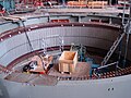
Runner of a salient pole machine of the Hoover Dam during the revision (The many poles of the runner are easy to see.)
Stand of a salient pole machine of the French Barrage de Marèges dam

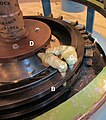
Slip rings and carbon brushes on the rotor of a synchronous generator in the Amsteg power plant

For a revision of "solid" rotor of a turbine generator
Slip ring apparatus of a hydrogen generator; Excitation current 500 A at 150 V.


application
The main applications of synchronous machines are three-phase generators in power plants . Almost the entire conventional production of electrical energy takes place with synchronous generators. In thermal power plants , full-pole machines with outputs of almost 2000 MVA and output voltages of 21 to 27 kV are used. The world's largest generator for the Finnish Olkiluoto nuclear power plant was manufactured in the Siemens plant in Mülheim . It has a rated apparent power of 1992 MVA. These generators, with their high-speed turbo rotors, are called turbo sets in conjunction with the turbines . The slow-moving salient pole machines in hydropower plants are called hydropower or hydrogen generators and deliver up to 1000 MVA at a maximum stator voltage of 25 kV. Generators with a lower output of 10 kVA to 10 MVA are used in small power plants and diesel generators and are usually also designed as salient pole machines. Synchronous generators for wind turbines are currently manufactured with an output of up to 8 MW. In addition, it is used to supply local networks. The synchronous generator is also used to provide electrical energy for the operation of rail vehicles and ship propulsion systems, as well as road vehicles in the future. The claw pole machine is a special design of the salient pole machine ; it is mainly used as a motor vehicle alternator (generator).

Hoover Dam salient pole generators

Machine house of the Walchensee power plant ; on the right the AEG salient pole generators, on the left Francis turbines
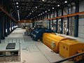
Modern turbo generator (yellow cylindrical unit in the middle); 800 MW; Black pump power plant machine house

Three-phase synchronous motor during assembly

French locomotive series BB 26000 with three-phase synchronous motors

Rotor of an electrically excited ring synchronous generator of an Enercon wind turbine


Three-phase synchronous motors with high power are used as drives for blowers , pumps and compressors and, in some cases, as rail drives ( SNCF BB 26000 , TGV , AGV ). With the option of speed control via frequency converters, the synchronous motor displaced large DC machines, but also gas turbines for driving turbo compressors . Motors with permanent magnets for auxiliary and vehicle drives are used in the low and medium power range. One application in the field of automation technology is the combination of two synchronous machines. This combination serves as a sensor and actuator to transmit the angular positions of the rotor and is also referred to as a resolver or a resolver transformer. In addition to synchronous machines, other machine types are also used as resolvers.
The synchronous motor in the Hammond organ is an example of the use of a small synchronous machine outside of power engineering .
economic aspects
The profitability of a machine is determined, among other things, by the acquisition and operating costs as well as the efficiency. The efficiency of the synchronous machine (approx. 95 ... 99% depending on the size and the required excitation power) is generally higher than that of the asynchronous machine due to the synchronous current and voltage phases. Large synchronous machines such as B. the turbo generator are therefore among the most efficient energy converters. Because of the excitation device of the synchronous machine, the structure of the synchronous machine is more complex than that of the asynchronous machine and therefore also more expensive. The cost of the control electronics is similar to that of the asynchronous machine. Permanent magnet synchronous machines achieve even higher levels of efficiency, as no excitation power has to be supplied to them. With the same performance and greater power density, the mass of the machines is reduced or the size is reduced. Generators of this type achieve an efficiency of over 98% in wind power plants and are thus higher than the efficiency of machines of the same size with electrical excitation. Permanent magnet excitation is only used in small to medium-sized machines. The costs for the magnets are becoming more and more important in larger machines, so that the economic efficiency compared to machines with electromagnetic excitation is no longer given. The complicated assembly of the magnets is also a major disadvantage.
The following manufacturers are a selection with some of their products in the field of synchronous machines:
- ABB - Asea Brown Boveri - Synchronous Motors and Generators
- AEM - Anhaltisches Elektromotorenwerk Dessau - Synchronous Generators and Motors
- General Electric - synchronous generators
- Leroy-Somer - drive technology and generators
- Lloyd Dynamowerke - synchronous generators and motors, high-voltage synchronous generators and motors, ship propulsion systems
- Loher - Permanent magnet synchronous motors and generators
- KSB SE / REEL - synchronous reluctance motors without permanent magnets
- Schorch Werke, Mönchengladbach ( ATB AG ) - drive technology and high-voltage synchronous motors
- Siemens - synchronous generators and motors, rail motors, permanent magnet servomotors
- VA Tech Elin EBG - synchronous generators and motors, synchronous rail motors
- VEM Group - synchronous generators, high-voltage synchronous motors, ship drives
Under high-voltage motors and high-voltage generators is understood machines with rated voltages above 1 kV. These designations come from the fact that voltages above 1 kV are referred to as high voltage in the VDE regulations .
Advantages and disadvantages
Advantages:
- High efficiency
- low mass moment of inertia
- low maintenance (if excitation without slip rings)
- Speed independent of load
- Relatively large air gap possible
- Reactive power control possible with electrical excitation (see phase shifter operation)
Disadvantage:
- Excitation power always required if not permanently excited or expensive material for permanent magnets
- high control effort (modern electronics)
- no self-start (without greater damping)
Operating modes
Generator operation


So that the synchronous machine can work as an electric generator, i.e. as a three-phase synchronous generator, an excitation field is necessary in the rotor circuit (internal pole machine). This means that a magnetic field (excitation field) must be generated by a DC- excited rotor winding ( excitation winding ) or a permanent magnet , which induces a stator voltage in the strands of the stator winding . The strands of the stator winding are linked to form a star . At the generator terminals is obtained (ends of the strands U, V, W) is a three-phase AC voltage , three phase-shifted by 120 ° alternating voltages. The stator phase voltage (also called terminal voltage) can be calculated as follows with knowledge of the synchronous reactance , the stator current and the pole wheel voltage :


When using an excitation winding, excitation power must be supplied to generate the excitation field. There are various excitation systems for this , for example the static excitation device or the brushless excitation device . In order to avoid damage to the generator in the event of sudden load shedding , a separate de-excitation circuit is provided for larger machines .
The number of pole pairs and the line frequency of the field winding are decisive for the rated speed of the generator, which is defined as follows:


If the rotating field speed (for synchronous machines rotating field speed = rotor speed) is related to minutes, the following applies:

For example, at a stator voltage frequency of 50 Hz = 50 / s · 60 s / min = 3000 min −1, a two-pole ( ) generator runs at 3000 min −1 and a four-pole ( ) generator runs at 1500 min −1 .


In addition, a work machine coupled to the generator shaft is necessary such. B. an internal combustion engine or a turbine that drives the rotor with the excitation field in rotation. This means that the driven machine supplies mechanical power to the generator, which the generator converts into electrical power. The mechanical power supplied and the active electrical power output are calculated as follows:
- , with the angular frequency (speed ) and the torque supplied by the drive machine
- , with the phase voltage , the phase current and the power factor


This equation is valid for star and delta connected machines. If related, non-absolute values are used for the calculation, the 3 must be removed.
If the losses are neglected, the following applies . With the real generator, however, there are hysteresis and current heat losses as well as friction losses . If you divide the electrical power dissipated by the mechanical power supplied, you get the efficiency of the machine, which is always less than 1, i.e. below 100%.

The flux linkage forms the relationship between the rotor speed and the induced rotor voltage .


The flux linkage can be determined in an idling test. To do this, the machine is driven at a known angular speed and the voltage is measured across one of the phases to the neutral conductor (in the simplified single-phase equivalent circuit, this corresponds to the voltage ). If a twelve-pole ( ) machine is also driven and a phase-to-neutral voltage of is measured, the result is a flux linkage of .


Summary of the mode of action:
- The generator is idling at the rated speed.
- The mains connection of the generator takes place when all synchronization conditions are established.
- Mechanical power is supplied via the drive machine.
- This would accelerate the generator, but the load from the electrical consumers in the network creates a counter-torque which counteracts the torque of the drive machine.
- A three-phase alternating current flows (stator current ).
- The stator current causes a differential voltage at the synchronous reactance (inductive reactance of the stator winding; ohmic resistance neglected).
- As a result of the voltage drop on , a rotor angle dependent on the stator current forms , which is always positive in the direction of rotation in generator mode.
- As a result, the pole wheel voltage shifts to the fixed line voltage (compared to idling) with the angle of the pole wheel in the direction of rotation.
- At constant torques, equilibrium and a constant rotor angle are created and the synchronous speed is maintained; fluctuating loads in the network can disturb this balance.


The stator voltage is load-dependent. With constant excitation current and constant speed, there are different characteristics for capacitive, inductive and ohmic loads. With a capacitive load there is an increase in voltage, for an ohmic load there is a slight drop and for an inductive load there is a strong drop in the stator voltage. In order to keep the stator voltage constant, the excitation current must be regulated according to the load. The regulation characteristic shows how the excitation current must be regulated according to the various loads: inductive load requires a strong increase in excitation current, resistive load a weak one. In order to counteract the strong increase in the stator voltage with a capacitive load, the excitation current must be reduced significantly. With generators in large power plants, the excitation current is kept constant. Here the voltage is regulated by means of a step switch on the downstream machine transformers .


Stator voltage at constant speed and constant excitation current

Regulation characteristic in isolated operation for constant terminal voltage


Synchronous generators can be damaged in asynchronous mains switching if no safety devices are effective. Incorrect synchronization of a generator results in equalizing currents, which in turn result in torques. Small incorrect synchronization and associated oscillations (caused by the torques) are reduced by the damper windings. Large incorrect synchronizations lead to damage to the generator, since the associated high torques affect the machine and the machine foundation. If a generator is to feed energy into a network, synchronization or parallel switching conditions must be met before synchronization :
- same level of mains and generator voltage
- same frequency of the mains and generator voltage
- same phase position
- same phase sequence
Various devices and circuits are available for synchronization (light or dark switching, synchronoscope ), but nowadays most people rely on automatic synchronization using digital control technology. After the synchronization conditions have been established, the generator is switched to the mains while idling and can then be electrically loaded, i.e. it can deliver electrical power.
Engine operation
For motor operation, as with generator operation, an excited rotor winding ( excitation winding ) or a permanent magnet is necessary in order to generate an excitation field. In addition, electrical energy must be supplied via the stator windings so that the three-phase synchronous motor can deliver a torque to the shaft. The electrical power consumed is calculated as follows:
- , with the concatenation factor , the stator voltage , the stator current and the power factor


The mechanical power output corresponds to the electrical power consumed minus the power loss component, which consists of copper and iron losses as well as friction losses.

- , with the circular frequency (speed in revolutions per second) and the torque demanded by the driven machine


The ratio of mechanical power delivered to electrical power consumed expresses the efficiency of the machine.
The simplified equivalent circuit diagram of the synchronous machine can be found in the section on generator operation. In the article three-phase machine, the drive principle is described by a rotating field, which applies to both synchronous and asynchronous motors.

Summary of the mode of action:
- The synchronous machine is idling on the rigid network.
- There is a load on the motor shaft from a machine.
- The motor would reduce its speed, but the motor now consumes electrical power and the stator current increases.
- An engine torque now acts which counteracts the load torque.
- The stator current causes a differential voltage at the synchronous reactance (inductive reactance of the stator winding; ohmic resistance neglected).
- As a result of the voltage drop on , a rotor angle that is dependent on the stator current is formed, which acts against the direction of rotation in motor operation.
- As a result, the pole wheel voltage shifts to the fixed line voltage (compared to idling → idle vector image see generator mode) with the angle of the pole wheel against the direction of rotation.
- The motor continues to run at synchronous speed; there is no slip as with an asynchronous motor.
Synchronous motors with low damping do not start on their own. The rotor of a synchronous motor usually has too large a mass moment of inertia to follow the rotating field from standstill. Therefore, the motor speed must be brought close to the rotating field speed without load. Then the excitation is switched on and the rotor of the motor is pulled into synchronous operation. The engine can then be loaded. Various methods are available for start-up:
- Starter motor
- A coupled starting motor (also starting motor) brings the speed of the synchronous motor close to the rotating field speed. After synchronization, the starter motor is decoupled.
- Asynchronous start-up through additional damper cage in the rotor circuit
- Thanks to the damper cage, the synchronous motor can start up on the principle of an asynchronous machine . If the motor speed reaches the rotating field speed after switching on the excitation, the damper cage loses its effect as a starting cage and the motor continues to run as a synchronous machine. When starting up, the field winding is mostly short-circuited via a resistor in order to avoid the induction of high voltages and to increase the starting torque.
- Frequency start
- The frequency of the supply voltage is continuously increased from zero to the rated frequency or the resulting rated rotating field speed. An outdated method for this is the frequency conversion by means of an upstream asynchronous generator . The frequency of the voltage output by the generator is increased via the supplied speed or its slip. Today, power electronic converters are used for frequency start-up. A load start-up is also possible with this procedure.
Phase shift operation

Phase shifter operation is an operating mode of the synchronous machine synchronized to the network, in which almost exclusively reactive power is drawn from the network or released into the network. The synchronous machine is operated in mechanical no-load operation, the comparatively low active power that is nevertheless consumed serves to cover losses such as thermal losses in the electrical windings or losses due to mechanical friction in the bearings.
By increasing or decreasing the excitation current, the amount of reactive power delivered to the grid or consumed from the grid is influenced. In the event of overexcitation, capacitive reactive power is emitted (behavior like capacitor) and under-excited the synchronous machine absorbs inductive reactive power (behavior like coil). The output of inductive reactive power corresponds to the absorption of capacitive reactive power and vice versa, according to the designation of the reactive power flow direction . The synchronous machine as a phase shifter is used primarily for load flow control in meshed power grids and secondarily for reactive power compensation .
As a rule, a synchronous machine is operated overexcited in phase shifter operation, since energy networks are usually more loaded by inductive than capacitive consumers. Energy networks take on a capacitive character due to line capacities when only a few consumers are connected to the network. In this case, the synchronous machine is operated under-excited in the phase shifting mode.
A distinction is made between machines which, due to their design, are used exclusively for phase shifting, the so-called phase shifters , and synchronous generators in phase shifting mode. The functional principles are identical in both cases, only the structure and design of the machine differ.
Phase shifters are synchronous motors specially designed only for this function and, as an essential feature, do not have a mechanical shaft leading to the outside . Depending on the excitation, they serve exclusively to provide inductive or capacitive reactive power in the supply network.
Synchronous generators in phase shifter operation, on the other hand, are conventional synchronous machines and are located, for example, in power plants that are operated as phase shifters from time to time and as required. For example, synchronous machines in pumped storage power plants that are not in pump or generator mode run in idle mode and can thus be used in phase shifter mode. In gas turbine power plants , the generator is separated from the gas turbine in phase shifter operation by means of a mechanical coupling in order to prevent additional active power losses caused by compression in the gas turbine.
V curve

If a synchronous machine is operated with constant mains voltage in phase-shifting mode, the V-curves named after their curve shape can be recorded. If you change the excitation current at different constant active powers and over- or under-excite the synchronous machine and then apply the resulting stator currents , you get the characteristic V-curves. The synchronous machine loaded with active current can also take over as much reactive current resulting from the overexcitation or underexcitation until the rated current is reached.

The figure shows five curves with the minima P 0 to P 4 , which result from different active to rated power ratios P S / P N. Only active power is converted in the minima of the curves, with reactive power to the left and right of it. The curve with the minimum P 0 is a pure phase-shifting operation, no real power is converted.
When the stability limit is reached, the machine falls out of step in motor mode or goes through in generator mode.
Current location curve

The operating behavior of synchronous machines can be represented with the current locus. Statements can be made on the operating mode, the degree of excitation and the operational stability of a synchronous machine. The formula for the stator voltage follows from the simplified equivalent circuit diagram (R S = 0; see generator operation):

The stator current can be derived from this:

In the locus , the pointer of the stator voltage lies in the real axis (Re) . Around the tip of the pointer there is a circle with the radius of . This radius is variable because of , so that there is a concentric family of current locus curves for the synchronous machine. With results in a degree of excitation of . The resulting circle goes through the origin of the Im-Re coordinate system.


Characteristic points and areas:
- : The locus becomes a point
- : underexcited operation
- as well as : overexcited operation
- : Phase shift operation
- : stable generator operation
- : stable engine operation


Field wave in the air gap

In order to better understand the functional principle of a synchronous machine, one should consider the field wave in the air gap. The picture opposite shows a two-pole synchronous machine (2 magnets , a north pole, a south pole) with a three-phase single-hole winding (6 strands, 6 slots). The machine is idling.
The x -axis (0 ° to 360 °) runs in the air gap and stands for the rotor circumference (which is specified here in degrees so that you do not have to be limited to a certain radius). The y- axis points upwards and gives the value for the magnetic flux density in Tesla (T) as a function of and . The z- axis describes the angle of rotation from 0 ° (corresponds in figure R1) to 180 ° (corresponds in figure R31), i.e. half a turn.


The effect of the two magnets can be clearly seen, which initially generate an approximately trapezoidal field of 10 ° to 170 ° or 190 ° to 350 °. The mean width of this trapezoid (about 140 °) corresponds roughly to the width of the magnet. This trapezoid is always present regardless of the angle of rotation ( z- axis).
The inclined "grooves" are created by the grooves: Where the groove is straight, the air gap is larger and represents a greater resistance for the magnetic flux, the flux density is lower at this point. Since the grooves rotate past the magnet, the groove appears at an angle in the diagram. If you follow a groove from to , you will see that it also runs through exactly 180 ° on the x -axis.


In order to generate a torque, a current must flow in the grooves that are exactly below the magnets. According to the principle of the Lorentz force

then the moment is generated.
In order to generate the maximum torque (which is also the breakdown torque), the normally sinusoidal current must be in phase with the field wave.
Applicable DIN standards and DIN VDE regulations
- DIN VDE 0530 part 1 to 18 or corresponding parts of DIN EN 60 034 or IEC 34
- DIN ISO 1940-1 - Requirements for the balance quality of rigid rotors; Determination of the permissible residual imbalance
- DIN ISO 7919-… - Mechanical vibrations of machines with the exception of piston machines - Measurement and evaluation of shaft vibrations
- DIN ISO 8821-… - Mechanical vibrations Agreement on the parallel key - type when balancing shafts and composite parts
- DIN ISO 10816-… - Mechanical vibrations - Evaluation of machine vibrations by measurements on non-rotating parts
Separate standards are also used for explosion-proof areas :
- DIN VDE 0165 - Setting up electrical systems in potentially explosive areas
- DIN VDE 0166 - Installation of electrical systems in areas endangered by explosive substances
- DIN EN 50014 - Electrical equipment for potentially explosive areas; General provisions
- DIN EN 50016 - Electrical equipment for potentially explosive areas; Pressurized enclosure "p"
- DIN EN 50019 - Electrical equipment for potentially explosive areas; Increased security "e"
Individual evidence
- ↑ Definition of terms according to International Electrotechnical Dictionary - IEV 411-31-08
- ^ Rolf Fischer: Electrical machines . 14th edition. Carl Hanser Verlag, Munich 2007, ISBN 978-3-446-41754-0 , pp. 291 ff . (updated and expanded edition).
- ^ A b Rolf Fischer: Electrical machines . 14th edition. Carl Hanser Verlag, Munich 2007, ISBN 978-3-446-41754-0 , pp. 324 ff . (updated and expanded edition).
- ^ A b Rolf Fischer: Electrical machines . 14th edition. Carl Hanser Verlag, Munich 2007, ISBN 978-3-446-41754-0 , pp. 313 ff . (updated and expanded edition).
- ↑ a b c d Rolf Fischer: Electrical machines . 14th edition. Carl Hanser Verlag, Munich 2007, ISBN 978-3-446-41754-0 , pp. 287 ff . (updated and expanded edition).
- ^ A b Germar Müller, Bernd Ponick: Fundamentals of electrical machines . 9th edition. Wiley-VCH, Berlin 2006, ISBN 3-527-40524-0 , pp. 485 ff . (completely revised edition).
- ^ Hans-Ulrich Giersch: Electrical machines . 5th edition. Teubner Verlag, 2003, ISBN 3-519-46821-2 , pp. 331 .
- ↑ Springerprofessional: The ideal electric motor for electric mobility. Retrieved August 18, 2015.
- ^ A b Germar Müller, Karl Vogt, Bernd Ponick : Calculation of electrical machines . Electrical machines. 6th edition. tape 2 . Wiley-VCH, 2007, ISBN 3-527-40525-9 , pp. 170–172 (completely revised edition).
- ↑ Germar Müller, Bernd Ponick: Basics of electrical machines . 9th edition. Wiley-VCH, Berlin 2006, ISBN 3-527-40524-0 , pp. 583 (completely revised edition).
- ↑ Prof. Dr.-Ing. Manfred Lindmayer, Dipl.-Ing. Jörn Grundmann, TU Braunschweig , Germany (Ed.): High-temperature superconductors in electrical power engineering equipment - state of research . S. 1–12 ( PDF 0.5 MB ).
- ^ Robert Gerlings: Farewell to 900 tons . Siemens delivers the world's largest generator. Ed .: WAZ . September 22, 2008 ( HTML [accessed January 3, 2011]).
- ↑ Solutions for wind energy. VEM Sachsenwerk GmbH , 2014, accessed on February 17, 2017 .
- ↑ Thomas Estler: Locomotives of the French state railway SNCF . 1st edition. Transpress, Stuttgart 2014, ISBN 978-3-613-71480-9 , pp. 61 .
- ↑ Henning Wallentowitz, Arndt Freialdenhoven, Ingo Olschewski: Strategies for the electrification of the drive train . 2nd Edition. Vieweg + Teubner Verlag, 2009, ISBN 3-8348-0847-4 , p. 81 .
- ↑ Erich Hau: Wind turbines . 4th edition. Springer-Verlag, 2008, ISBN 3-540-72150-9 , pp. 356, 362 .
- ↑ Germar Müller, Bernd Ponick: Basics of electrical machines . 9th edition. Wiley-VCH, Berlin 2006, ISBN 3-527-40524-0 , pp. 580 (completely revised edition).
- ^ Rolf Fischer: Electrical machines . 14th edition. Carl Hanser Verlag, Munich 2007, ISBN 978-3-446-41754-0 , pp. 297 (updated and expanded edition).
- ↑ Germar Müller, Karl Vogt, Bernd Ponick: Calculation of electrical machines . Electrical machines. 6th edition. tape 2 . Wiley-VCH, 2007, ISBN 3-527-40525-9 , pp. 195 ff . (completely revised edition).
- ↑ Ed. Committee 311: Rotating electrical machines: Explanations to DIN EN 60034 (VDE 0530), Volume 10 , 7th edition. VDE Verlag, 2004, ISBN 3-8007-2848-6 .
literature
- Peter-Klaus Budig: Converter-fed synchronous machine . Theory and applications. VDE-Verlag, Berlin 2003, ISBN 3-8007-2518-5 .