Fuldatalbrücke Kragenhof
Coordinates: 51 ° 21 ′ 28 ″ N , 9 ° 33 ′ 8 ″ E
| Fuldatalbrücke Kragenhof | ||
|---|---|---|
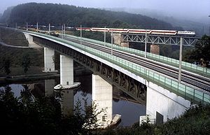
| The completed bridge, still without an overhead line | ||
| Convicted |
High- speed line from Hanover to Würzburg |
|
| Subjugated | Fulda | |
| place | kassel | |
| construction | Steel truss composite bridge |
|
| overall length | 249.6 m | |
| width | 13.5 m | |
| Longest span | 73.6 m | |
| Construction height | 8.1 m | |
| height | 30 m | |
| start of building | 1986 | |
| completion | 1988 | |
| location | ||
|
|
||
The Fuldatalbrücke Kragenhof is a 249.6 m long double-track railway overpass structure on the high-speed line Hanover – Würzburg at route kilometers 133.2. To the north of the bridge is the 1,345 m long Mühlenkopf tunnel . To the south, after a section of open road, the Lohberg tunnel follows .
The four-span girder bridge is located near Fuldatal north of Kassel and spans the Fulda with the state border between Hesse and Lower Saxony and the Fuldatalstrasse L 3235 at a maximum height of 30 m above ground. It is the only steel framework composite bridge on the high-speed line. The half-timbered construction was chosen based on the neighboring Fuldatalbrücke Kragenhof from 1855 of the Hannöverschen Südbahn (Hann. Münden – Kassel) . At a line speed of 160 km / h, the route in the bridge area has a radius of 1,552 m and has no longitudinal gradient. There are three rail extensions.
The structure was tendered in two lots and awarded in September 1985. It was built between October 1986 and November 1988. The client was the project group NBS in Bundesbahndirektion Frankfurt of the German Federal Railroad . The cost was about 14 million DM.
In a southerly direction, the bridge marks the beginning of a 9 km long section in which the new construction and north-south sections run parallel through Kassel.
Foundation and substructures
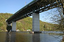
The three pillars are each founded on 15 large bored piles with a diameter of 1.5 m and a length of approximately 17 m. Their wall thickness is up to 50 cm. The abutments have a flat foundation . The rectangular reinforced concrete pillars with a maximum height of 20 m have a hollow box cross-section with a maximum width of 3.55 m. They taper upwards with a suit of 80: 1.
The western abutment stands on an up to 23 m high and 200 m long dam and forms the fixed point of the bridge.
To produce the foundation, 2,200 m³ of sheet pile walls were built. A total of 500 m of bored piles, 7,400 m³ of concrete and 550 t of steel were used.
superstructure
The 8.1 m high superstructure is designed as a composite structure and consists of two postless strut trusses made of steel with a reinforced concrete slab on top . The 13.5 m wide carriageway slab has the cross-sectional shape of a plate beam . It is up to 40 cm thick and has a height of 1.1 m above the main girders, which are arranged at a distance of 5.6 m. The superstructure consists of a chain of four single-span girders . This enables individual bridge segments to be replaced later.
The total span of the bridge is 249.6 m, 58.4 m for the peripheral fields and 73.6 m or 59.2 m for the inner fields.
history
planning
In the pre-routing of the new line from 1972/1973, the Göttingen variant was intended to cross the Fulda downstream, at Wilhelmshausen .
Due to the course of the state border in the middle of the Fulda, the border between the planning areas north and middle of the route also ran in the planning and construction phase.
construction
The steel superstructure was delivered in individual parts by truck. The final welding was carried out on the southern abutment, with the steel structure being inserted in sections of 20 to 30 m in length. For this purpose, the half-timbered structures of the individual superstructures were coupled to form a continuous beam . The reinforced concrete deck slab was then produced in sections with lengths of 13 to 17 m using a formwork carriage . Finally, the couplings of the continuous beam were separated in order to produce the single-span system.
The structure was completed in 1988.
literature
- N. Keller, R. Kahmann and M. Krips: Fuldatalbrücke Kragenhof . In: civil engineer. 63. 1988.
Individual evidence
- ↑ a b c d e f g h Wayss & Freytag AG: Structures in the course of the new Hanover – Würzburg line of the Deutsche Bundesbahn in the Kassel area . ( Technical sheets of Wayss & Freytag AG , 1/88), 16 pages, p. 2, 11–15
- ↑ Helmut Weber, Walter Engels, Helmut Maak: The new Hanover – Würzburg line . In: Railway technical review . 28, No. 10, 1979, pp. 725-734.
- ↑ Central Transport Management Mainz (ed.): New Hanover-Gemünden line . Plan 410.4101Nv101. Edited in January 1972 Langhanki , drawn in January 1972 Bönjer , plan dated February 1, 1972 as of November 20, 1973, sheet 2 of 2.
- ^ DB project group Hanover-Würzburg (North) (Ed.): New Hanover-Würzburg line: Rosdorf, Mengershausen , brochure (12 pages, folded) as of September 1, 1983
- ↑ Without author: Annual review 1988 . In: The Federal Railroad. Vol. 65, No. 1, 1989, ISSN 0007-5876 , p. 61.


