
Geological compass


The geological compass is a compass that is primarily used to determine the spatial position of rock structures (especially dividing surfaces ). In addition, it is also used for geological mapping and orientation in the terrain . For this reason, it is common for geologists compasses usually a combination of surveyor compass (with inclinometer ) and marching compass (with visor and mirrors).
use

In geology, the spatial position of surfaces (such as bedding planes , foliation surfaces , fault planes , etc.) defined by two values:
- The stroke is the imaginary line of intersection of the surface in question with the horizontal , i.e. with the map plane.
- The fall is the maximum angle between this surface and the horizontal. The direction of fall (i.e. the direction in which a marble would roll on this surface) is always at right angles to the stroke.
These two values make it possible to enter a geological area in the correct position in maps, profiles or 3-D models or to use it digitally.
Measurement of the strike
With the geological compass, in contrast to the marching compass, the compass rose is fixed and the needle immediately shows the direction ( azimuth ) of the stroke. The compass rose is therefore mirror-inverted for correct reading.
For small-scale measurements, e.g. B. to shift and foliation faces , an edge of the compass is applied to the surface to be measured and, with the aid of a spirit level adjusted in the horizontal. The stroke can now be read directly. In the case of large-scale structures, such as the outcrop of a rock or ore vein in reasonably flat terrain, the painting can also be assessed "freehand" over the structure.
Most geological compasses have a compass rose with a graduation of 360 ° in order to enable orientation in the field by means of bearings via the visor. As with a marching compass, the azimuth is read off the mirror. Since a streak line of z. B. 135 ° (southeast) but at the same time always pointing to 315 ° (northwest), half of the 360 ° scale is actually redundant for measuring the strike direction. That is why there are also compasses in which the rose is divided into four quadrants. North and south are assigned the values 0, while east and west are assigned 90. The strike direction northwest-southeast is then noted as N 045 W.
Measurement of fall
For this purpose, an edge is created at a right angle to the previously determined streak line with conventional geological compasses. The angle of fall is then read from the built-in inclinometer. The inclinometer is usually equipped with a second level, in case it does not simply level off by itself due to gravity. Horizontal surfaces have a fall of 0 °, vertical surfaces of 90 °. It should be noted that z. B. an area with a strike direction northwest-southeast can now invade both northeast or southwest. This must be noted in the complete measurement: 135 ° / 50 ° SW or N 045 W / 50 ° SW
Structure compass

Structure of the structural compass (Freiberger), side view

Top view

Bottom view

_de.svg)
_de.svg)
The concept of the structure compass was developed by Eberhard Clar at the University of Vienna . He published his concept of the two-circle compass for the first time in 1954. This was taken up by VEB Freiberger Precision Mechanics and made ready for series production in close cooperation with the Technical University of Freiberg .
A special form of the geological compass is the structure compass, with which the spatial position of an area can be determined in a single measurement. Here, it is not the fall and stroke that is measured, but the angle and direction of fall. The cover of the structural compass serves as a protractor. The flap is placed on the layer surface, and after the compass has been weighed in with the aid of the level, the compass needle is fixed with a lock. Then the angle of fall can be read on a scale on the lid hinge (height circle), the direction of fall on the compass rose. Since the direction of fall is read on a 360 ° scale, the value is clear, the notation for the above example would then be: 225/50 . The strike can now be calculated simply by adding or subtracting the direction of fall with 90 ° (315 or 135). The company Freiberger Präzisionsmechanik offers, in addition to the commonly used degrees, the division into gons , which enables a much more precise division. When specified in gons, the height circle (for reading the angle of incidence) and the clinometer graduation (the division on the pendulum of the clinometer to determine the angle of incidence) are each divided into 100 gons instead of 90 °. In these devices, the compass pitch circle is also divided into 400 gon instead of 360 °.
Because of the speed and clarity of the measurement, structural compasses are particularly suitable for collecting large amounts of structural geological data. Since the scale on the lid hinge is not very precise, a second, pendulum-shaped inclinometer (clinometer) can also be used for more precise measurement of the angle of fall. Orientation in the terrain is only possible to a limited extent with a structural compass, since the directions of the compass are also mirror-inverted here for quick determination of the values. Please note that the north and south needles are also swapped (north is black and south is red). Should this compass be used for orientation in the field, the direction you are aiming for is read off the red marked south needle.
With the structure compass, however, it is not only possible to measure the angle of incidence and the direction of incidence of geological structures, but also to measure lineations on certain surfaces. Lineations are mineral orientations on geological surfaces such as armor surfaces, foliation surfaces and the like. A side edge of the attachment flap is placed directly on the lineation and the compass body is aligned using the level indicator. The direction of fall and the angle of fall of the lineation can then be read off directly, even if the fall values of the lineation do not match the fall values of the interface on which the lineation lies.
Execution of the structure compass
When it comes to structural compasses in Europe, mainly the models from Freiberger Präzisionsmechanik and from Breithaupt have established themselves . These devices do not differ much from the basic structure. However, the clinometer in the Freiberg Precision Mechanics models is based on the principle of a freely swinging pendulum (if the compass is placed directly on edge at 90 °). When you fold the compass from the upright position to the normal position, the pendulum rests on the bottom of the compass and can therefore no longer move and change the value. In the case of the Breithaupt compass, on the other hand, the clinometer indicator consists of a sphere that runs in a semicircular path. The negative thing about this principle is that the ball can still move after the compass is folded back and thus falsifies the value.
The European market is flooded with many "inexpensive" imitations of these two models. The compasses from Freiberger Präzisionsmechanik and Breithaupt are very expensive to buy. However, the high costs justify the fact that the structural compasses are milled and assembled by hand and they are very robustly constructed.

Breithaupt microstructural compass COCLA
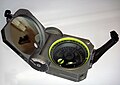
Brunton Pocket Transit, this shows the characteristics of the classic geological and the modern structural compass

Freiberg structure compass from FPM

Chinese structure compass

Russian structural compass


Web links
- Comparison of different geological compasses. (pdf, 509 kB) Uni Potsdam, accessed on March 10, 2013 .
- Geologist & Artillery Compasses. Retrieved March 10, 2013 .
Individual evidence
- ↑ A two-circle geologist and miner's compass for measuring areas and linear lines. -Comp. Geol.B.A., 201-215.
- ^ Geologist's compass. (PDF, 527 kB) Operating manual. Freiberg Precision Mechanics, accessed on February 15, 2015 (English).