Logical connection
A logical link is a Boolean algebra operation . With the help of the logical connections, more complex statements can be put together from simpler statements in propositional logic and switching algebra . The truth value of the composite statement must be uniquely determined by the truth values of the simpler statements contained, for example by a truth table (truth table). A truth table is the definition of a logical connection. Several input signals (1, 2, 3 or more) are combined to form one output signal (2 or more output signals are also possible) by means of a logical link. The logical connection defines the principles and logical relationships between the input signal and the output signal.
Link types
Logical links are also called sentence operators. The operators of the logical connection are called Boolean operators . Important two-digit logical connections are conjunction , disjunction , implication and equivalence . In digital technology, AND, OR, NOT, NOR, and NAND are the most common basic logic circuits.

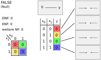
1. Contradiction
2. Conjunction (AND connection)
3. Inhibition (AND connection with input negation)
4. Identity of a
5. Inhibition (AND connection with input negation)
6. Identity of b
7. Antivalence (XOR connection)
8 . Disjunction (OR link)

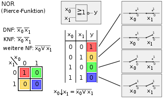
9. Peirce function (NOR link)
10. Equivalence (NXOR link)
11. Negation of b
12. Implication from b (OR link with input
negation ) 13. Negation of a
14. Implication from a (OR link with Input negation)
15. Sheffer function (NAND operation)
16. Tautology
In analogy to the mathematical term , one speaks of one- digit (Fig. 5) and two-digit (Fig. 1 and 2) links - depending on how many statements are put together. Higher-order links (e.g. three-digit link - images ) are of secondary importance here because they can be expressed using one- and two-digit links. The symbols with which the logical connections are expressed are called joiners .
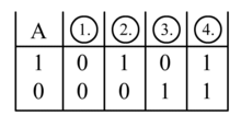
Among the one-digit logical connections there is only one non-trivial one, namely the negation .
The logical connections are used in practice as search operators in databases, queries to search engines and in digital technology . The practical implementation of logical connections in digital technology is carried out using logical circuits. Logical links are the basic elements of digital technology - for example in circuit design or in digital control technology.
Another practical application of the logical links is in higher-level programming languages , which mostly only know the links AND, OR and NOT, so that the other logical links must be constructed from these three components. Programming languages only work with two-character logical expressions. Multi-character logical expressions must also be formed by combining several two-character logical expressions.
The definition set and the target set of the logical connection are each W = {w, f}, where 'w' stands for true and 'f' for false . Other spellings are:
- W = {1, 0},
- W = {TRUE, FALSE},
- W = {TRUE, FALSE}.
Two-digit logical link
If you combine two logical variables, a total of 16 different results are possible. A function table with two-digit logical (Fig. 1) links (2 inputs) has a total of four lines, i.e. four different possible combinations of the input signals. As a result, 16 different results are possible (2 4 = 16) - picture 1 and 2. Each of the 16 possible two-valued links has a name. There are 16 possible two-digit operators.
Columns 1 to 8 (Fig. 1) symmetrically represent the negations of columns 9 to 16 (Fig. 2). In the remaining figures, the logic circuit symbol according to EN 60617-12 is shown in the top center , the electrical circuit on the right and in the Bottom middle the truth table ; At the bottom left is the Karnaugh-Veitch diagram , at the top left are the disjunctive normal form , the conjunctive normal form and, if necessary, another normal form .
In digital technology, the function of logical links is implemented using logic gates ; the other common symbols are also shown in the article logic gate .
|

Fig. 1, column 16:
TRUE (regardless of the input, the result is always "one") - tautology - a tautology is always true. There are an infinite number of tautologies - for example: A OR NOT A. |
|
|
|
|
|
|
|
|
|
|
|

Figure 1, column 8:
OR ( disjunction ) - The output is 1 if one or two inputs are 1 - At least 1 partial expression must be true for the whole expression to be true. |

Figure 1, column 9:
NOR ( Peirce function ) - combination of OR and NOT connected in series - 0 is present at the output if 1 is present at at least one of the inputs. - NOR behaves inversely to OR. |
|

Fig. 1, column 7:
XOR ( non-equivalence , exclusive OR) - The output is 1 if the inputs are different. - If both inputs have different logic states, output 1 is output. - Output is 1 only if exactly one input is 1. |

Figure 1, column 10:
XNOR ( equivalence ) - XNOR is the opposite of XOR, i.e. a combination of XOR and NOT connected in series. - If both inputs have identical logic states, output 1 is output. |
|
|
|
|

Figure 1, column 14:
Subjunction ( implication ) (from A to B) - If A is false (0) or B is true (1), then the result is true. |

Image 1, column 12:
Subjunction (replication) (from B to A) - If B is false (0) or A is true (1), then the result is true. |
- The IEC 60617-12 symbolism of the XOR and XNOR gates is swapped! XOR has no negation at the end of the link.
Logical linking in computer languages
Higher computer languages, in particular C , C ++ , C # , Java and PHP , know the abbreviated evaluation , the so-called short-circuit evaluation , the logical operators for AND or OR. The abbreviated evaluation is used to optimize the runtime and to avoid errors that would occur without the abbreviation (e.g. x == 0 || a/x == 2). The operator &&(AND) denotes the abbreviated evaluation of the conjunction. If the first input variable is already FALSE, then the second does not have to be considered in more detail, because the result is already known - it must be FALSE. The operator is &used if the abbreviated evaluation is not required . Similarly, the operator ||(OR) for the abbreviated evaluation and the operator |for the non-abbreviated evaluation of the OR function are used for the disjunction . With the OR function, the final result is TRUE if the first input variable is TRUE. The further evaluation of the logical connection can then be canceled. There are certainly reasons such as side effects or the intended exception handling that justify the existence of the operators for unconditional evaluation of both operands.
In Visual Basic .NET , short-circuit evaluations are generated using the special keywords AndAlso or OrElse.
Three-digit logical link
With three input variables (A, B, C) there are 8 possible combinations (the table has 8 lines). There are 256 eight-digit binary numbers from 0000.0000 to 1111.1111 (2 8 = 256). Thus, a three-valued logic operation has 256 possible different results. Very few of them have a generally binding name. The figures show the beginning and end of the 256 possible combinations.
The above statements only apply to binary logic , in which a statement can only have the value 0 or 1, but not for three-valued or similar multivalued logic systems .
|
||||||||||||||||||||||||||||||||||||
| Operator: (A AND B AND NOT -C) OR (A AND NOT -B AND C) OR ( NOT -A AND NOT -B AND C) |
Single-digit logical link
The figure shows all four possibilities of a single-digit logical link.
Multiple logical outputs
Further variation possibilities arise if instead of one result (with logical digital circuits: one output) there are several results (with logical digital circuits: several outputs) - for example with a 1-out-of-n decoder (2 inputs, 4 outputs) or full adder (3 inputs) , 2 outputs).
Fuzzy logic
In fuzzy logic , the logical operations of Boolean algebra are replaced by fuzzy operations.
literature
- Klaus Beuth: Digital technology - electronics 4 . 12th edition. Vogel Fachbuchverlag, 2003, ISBN 3-8023-1958-3


